(LCD screen : last updated by Benjamin on Decembre 16, 2022)
The selection of which LCD screen to use will depend on many factors. The connexion interface is the first to consider, followed by availability and quality of libraries, then brightness. The size and definition will depend on the software application using the screen and the space available on the instrument panel. For an EFIS or an EMS, to ensure excellent readability in all circumstances on the instrument panel, a size of 4.3 to 5 inches, a definition of 480 × 272 pixels or more, and a minimum brightness of 500 cd/m² are a good compromise. IPS technology offers much wider viewing angles.
Touch screen or not? It is a matter of personal choice: during flight, finger selection of a small screen area or menu option may be difficult during turbulence on a 5-inch (or less) display. Other control systems can be considered, such as push buttons, rotary encoders, or joysticks, often more precise than a capacitive touch screen. The latter also has the disadvantage of being glossy, while an anti-glare mat screen is much more readable under direct sunlight.
LCD screen interface
There are several display interfaces, including HDMI, parallel, and serial, to cite the most commonly used.
HDMI interface
Microcontroller boards never embed an HDMI-type display connector. Single board computers, such as the Raspberry Pi under Linux or the LattePanda under Windows, have such an interface. There are many others. But computers, particularly their operating systems, are hardly compatible with power loss; they must be powered off cleanly.
Embedded systems need to be designed so that any unexpected power loss (such as switching off the master switch on an aircraft) will not cause corruption in the operating system or data loss from the application software running on the device.
To be operated safely in an embedded application, a single-board computer requires measures to secure its power supply (such as this one for Raspberry), which gives the operating system the necessary time to shut down properly. In the context of a DIY project, the system is, therefore, more complex and at increased risk of failure. Microcontrollers are better suited to embedded tasks; turning off the power is their standard shutdown procedure. In addition, 5 inches or less, sunlight-readable HDMI displays are rare and seldom orientable in both portrait and landscape mode. For these reasons, HDMI displays are neither suitable nor easy to use in our avionics applications. The graphics computing power of a single board computer, associated with graphics software such as Processing, is undoubtedly much greater than that of a microcontroller … But we will see that there are alternatives.
Parallel interface
With parallel interfaces, each bit of each color (red, green, blue) is transmitted on a separate line. So 24 lines are required if each color is coded on 8 bits, plus several other lines for vertical and horizontal synchronization. Many microcontroller boards do not have a sufficient number of pins. A few rare (and expensive) prototyping boards use a high-end microcontroller that embeds a high-performance graphics controller. Few of these boards expose a parallel interface via a suitable output port, for example, the MIPI-DSI port on specific STM32 boards or the Arduino Portenta. These boards are instead reserved for industrial and professional applications; they go a little outside the field of “DIY,” i.e., the domain of the amateur to whom this site is intended. The display screens adapted to these boards are rare, often not very bright, and the libraries are inexistent or inaccessible… The advantage of such parallel RGB graphics controllers is their high refresh rate (50 frames/second and above) combined with double or triple frame buffering. These features ensure perfect display fluidity without any flickering. These controllers require a lot of resources, especially memory, but it allows fast animations without the slightest flicker. Unfortunately, this type of interface hardly meets the essential principles of the specifications on the home page: simplicity and economy.
Serial interface
This is the most suitable category of interface for microcontrollers. Screen serial interface can use i2c or SPI protocol.
I2C
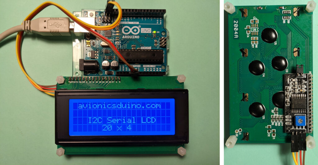
I2C can control a device with just two I/O pins: SDA and SCL. Several devices can coexist within a network on the same bus, as long as they have different addresses. This bus is relatively slow, ideally suited to sensors, less to screens. Some alphanumeric monochrome LCDs, such as the one in Figure 1, although having a parallel interface as standard, can be connected to an I2C bus using a parallel to I2C interface board located on the back of the display. To display a few lines of text, the I2C bus is more than sufficient. A screen of this type could have its place in avionics, for example, to display some engine parameters, the position of a trim, the settings of an autopilot, etc.
SPI LCD display screen
Due to the rudimentary and somewhat outdated aspect of monochrome alphanumeric displays, color graphics displays are generally preferred. Especially since their cost is often equivalent. TFT technology is by far the most widespread. SPI connection is the rule. TFT displays with SPI interface have various controllers: ILI9341, ST7735, HX8357, and RA8875 … to name a few. Their sizes vary from less than 2 inches diagonally up to 7 inches. Their definitions range from 128 x 160 to 800 x 480 pixels, sometimes with a touch interface.
The SPI interface is significantly faster than the I2C one; it uses four wires: MISO, MOSI, CLK, and CS. It suits these TFT screens and personal avionics systems’ needs. However, this interface has some drawbacks compared to parallel interfaces: there is no possibility of synchronization between the microcontroller and the timing signals of the display. In addition, the controllers of these screens do not embed multiple frame buffers. This can lead to annoying flickering phenomena on fast animations, manifested by flickering, dark lines, or bands that scroll vertically. The animations are to be used sparingly. The best way to remove any flickering is to update only the areas of the screen that change and keep those areas as small as possible. These prevention principles are impossible to apply in the example of video 1, where a large circular surface is moving. The circle is successively displayed, then erased by drawing an identical circle with the background color (here black), then displayed again in green at the next location: flickering guaranteed! You should not think of programming a video game with moving sprites using a microcontroller and a TFT SPI screen!
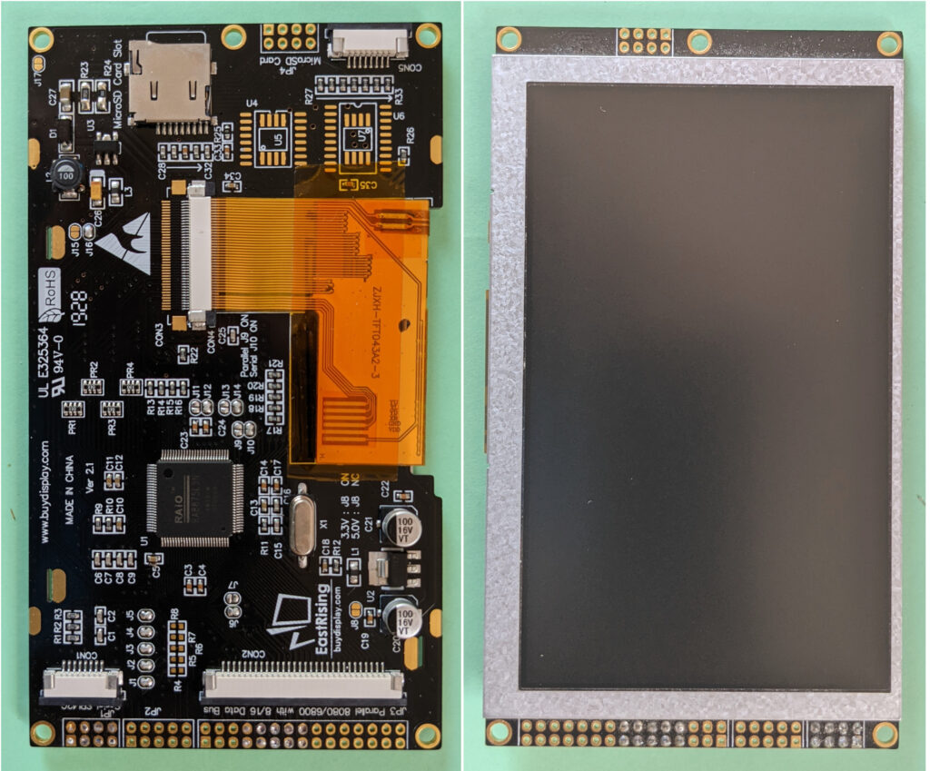
Fortunately, avionics displays can do without sprites. However, displaying the artificial horizon of an EFIS can be a real challenge. It is necessary to display many textual and graphic objects (which may vary quickly) on a mobile background representing the sky in blue and the earth in ocher. To overcome this difficulty, for our EFIS project, we chose to use a display equipped with a RA8875 controller. The latter serves as an interface between the microcontroller, to which it is connected in SPI, and the LCD-TFT panel to which it is connected via a parallel interface (Fig. 2). The RA8875 allows two different layers to be managed separately, each with its dedicated memory, which brings it closer to the principle of double frame buffering. This controller also benefits from an exceptionally efficient and fast library optimized for Teensy boards.
The main drawback of this library, which is the price to pay for its speed, is that it does not handle attempts to display pixels outside of the coordinates allowed by the screen definition. It is up to the programmer to either manage these overruns at the cost of slowing the calculations or to avoid them. The second solution was chosen, which led to making a small concession on the usual appearance of an artificial horizon: the pitch graduations rotate with the horizon, but do not move vertically with it, see video 2. A better solution might be adopted later…
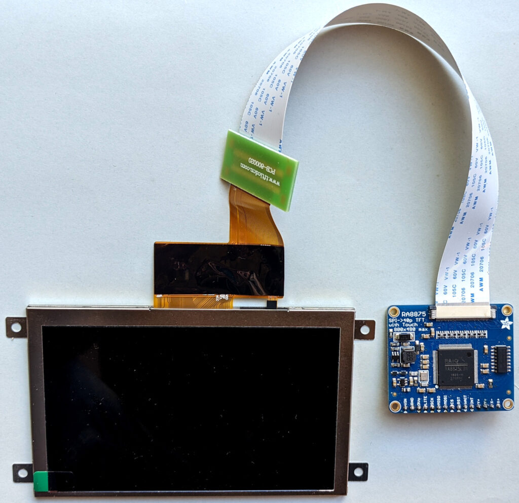
The EastRising / BuyDisplay displays have a few additional functions that are not useful for our projects: micro SD slot, SPI Flash memory, and keyboard slots. In addition, they show a certain tendency to malfunction, for example, when the SPI connection exceeds a few centimeters or when a solderless breadboard is used for testing. Incomprehensible black screens are not uncommon. For these reasons, we prefer to use the far more reliable Adafruit RA8875 controller and a separate panel, like this one and that one that have the significant advantage of IPS technology (Wide Viewing Angles). This allows greater flexibility in the arrangement of elements when installed on the instrument panel. Indeed, the RA8875 controller board can be integrated on the same PCB as the Teensy board, which guarantees the most reliable and shortest possible SPI connection. In addition, unlike the SPI connection, the parallel connection (40 conductor FFC cable) between the RA8875 controller and the LCD panel can be extended without inconvenience thanks to a 20 cm extension (Fig 3). See EFIS page.
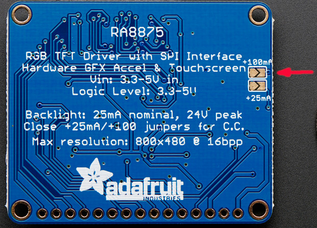
High-brightness 5″ LCD panels require more backlight power current than 4.3″ panels. For this reason, it is necessary to solder the two pads labeled “+100mA” on the back of the RA8875 controller (fig. 4).
Thanks for the quick reply. I did find the ra8875 on digikey yesterday, I didn’t see it in my earlier searches but probably just missed it. I have a couple on the way.
Thanks again.
Ron
Hello Ron,
Thanks for your kind comment.
Digikey has 133 in stock ! You can order now, you’ll receive the board in 3-4 days.
Unfortunately, there is no satisfactory alternative, the RA8875 is perfectly suited for this task with its two layers, and a highly optimized library is available for Teensy 4.x. Real Time animation of an artificiel horizon over SPI is a true challenge !
Benjamin
Hi,
This project is great work for anyone who’s hobbies include electronics and flying. Great work.
My question is, with the RA8875 controller nearly impossible to find, do you have a reliable second recomendation for a screen driver that you may have tested with the other hardware? Im looking at using the teensy board only for a build but can’t find the 8875 available.
Thank You
Hi Will,
Arduino, Teensy, STM32, and other microcontrollers never have an HDMI socket. An HDMI display would therefore require a single-board computer with HDMI connectivity. The operating system of these single-board computers (usually Linux) does not support sudden power loss, which requires securing this power supply using an uninterruptible power source (UPS). We are considering (with low priority) an EFIS solution based on a Raspberry PI, which would (slightly) improve the overall graphics performance, but the costs and overall complexity would increase significantly.
This would take us away from one of our goals: simplicity and low cost…
Benjamin
Hi,
amazing work, you’ve made me re think my entire panel (:
You had mentioned that perhaps you would be working on a solution for the HDMI screen to run ( display ) EFIS, just curious whether this was something you were still planning on re visiting .
Thank you for sharing all of this, truly brilliant!