(AHRS: Last updated by Benjamin on March 23, 2024)
The AHRS, for Attitude and Heading Reference System, is the most complex part of the EFIS. Not so much because of the components (particularly the IMU, see below), because they are ubiquitous, easy to find on breakout boards, and inexpensive. This complexity is actually due to the sensor fusion software, which fuses the raw data of all the sensors, computes the aircraft orientation in three-dimensional space, and outputs angles that characterize the aircraft position: heading, pitch, and roll. This software uses complex mathematical concepts rarely mastered by an amateur, even a seasoned one.
The components of the AHRS
Therefore, the hardware is very accessible. This is why there are many achievements on the web that may seem successful for some. Without taking much risk of being wrong, we can say that they have never been successfully tested in flight.
The heart of an AHRS consists of an inertial unit (gyrometer and accelerometer, each on three axes) generally coupled to a triaxial magnetometer.
Current technologies are not based on mechanical gyroscopes but on miniaturized semiconductor components, without rotating parts, the so-called MEMS, for Micro Electro Mechanical Systems. It is easy to find on the market, for a few euros, inertial units (or IMU, for Inertial Measurement Unit) based on MEMS, combining a triaxial accelerometer, a triaxial gyrometer, a triaxial magnetometer, and sometimes a 32-bit microcontroller ensuring the fusion of the data from these nine sensors to provide the user with clear absolute orientation in the form of the three angles well known to all pilots: heading, pitch, and roll.
The problem of the flight mechanics of fixed-wing airplanes
Among the most well-known IMUs of this type are the BNO055 from Bosch and the MPU9250 from InvenSense. There are many others that are newer and more efficient. These 9 degrees of freedom IMUs are used extensively as orientation sensors in flight controllers for multirotor drones, in smartphones, in the automotive industry, in robotics … etc. But when looking to use them in a fixed-wing aircraft, they all pose the same crippling problem. This problem is intimately linked to the flight mechanics of fixed-wing aircraft, which has nothing to do with multi-rotor drones or ground vehicles and applications for which these IMUs might have been designed.
Let’s take, for example, a BNO055, the best-known and most widespread in the Arduino community, and use it as AHRS for an artificial horizon. Comfortably seated in front of a desktop, everything is going as expected. In static mode, the attitude indicated on the screen is strictly identical to that imposed manually on this “AHRS.” Now, let’s take this same system in a fixed-wing aircraft.
During straight-and-level, coordinated flight, the horizon bar remains strictly horizontal. Small movements of the flight controls, with rapid return to straight and level flight, are perfectly reproduced on the screen. Let’s quickly get the plane into a level turn stabilized at a 30 ° bank. As the turn begins, the horizon shows it for a brief moment. But after a second or two, it starts to level out, and progressively, after two or three additional seconds, the display shows straight and level flight again while the aircraft is still in a 30° turn! Such an AHRS is useless!
This phenomenon is explained by the fact that the BNO055, like all other IMUs with 6 or 9 degrees of freedom, cannot distinguish the acceleration due to the earth’s gravity from the centrifugal one due to the turn.
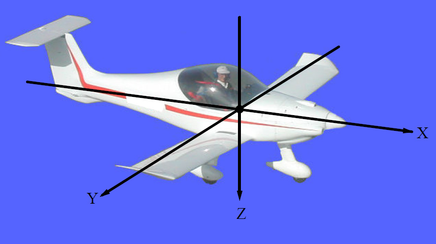
If there is an acceleration only on the Z axis and none on the X and Y axes (see Figure 1), and this is the case during a coordinated turn, the BNO055 and other IMUs in this category wrongly deduce that the airplane is horizontal in the earth reference frame. The acceleration resulting from the sum of gravity and centrifugal acceleration vectors is misinterpreted as being related to gravity alone. In IMC, our inner ear is deceived in the same way.
Therefore, these IMUs lack the means to isolate the inertial vector from the non-inertial vector for calculating the aircraft’s attitude relative to the Galilean (or inertial) earth frame of reference.
How do we solve the problem?
Those interested in the flight mechanics of fixed-wing aircraft will remember that the bank of a turning plane can be determined by knowing the radius of the turn and the speed on the path. In flight, the radius of the turn is not easy to measure, but it can be deduced from the aircraft’s speed and yaw rate (or angular speed).
These additional data are, therefore, essential for calculating the roll angle. Commercial EFIS have two solutions to recover this data: either they use, in addition to the gyrometers (which are always affected by a more or less rapid drift), an integrated magnetometer to help calculate the angular speed and are connected to the circuits of static AND dynamic pressures to calculate the speed of the airplane, or they use the data of a GPS/GNSS which provides the ground speed, the true course (track), and much other helpful information. Most often, both solutions are used to be able to rely on at least one data source in the event of failure of the other.
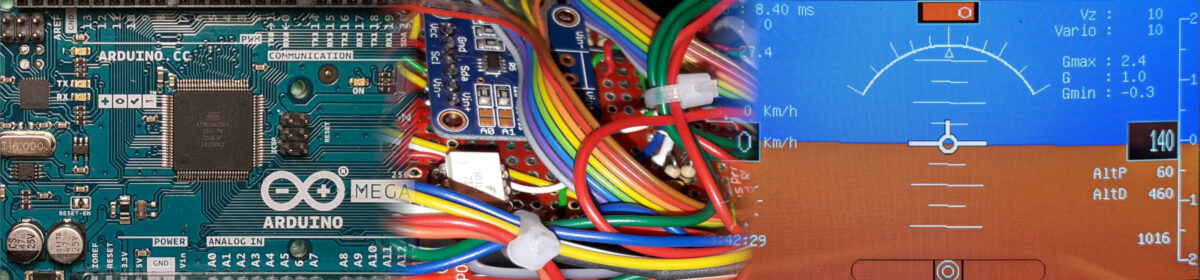
The math necessary for this data fusion calls for particularly complex notions beyond the capabilities of a non-specialist. Lacking the required skills in this area, we had initially to find a professional solution for our EFIS. The Naveol Company initially provided us with an AHRS prototype integrating a Ublox GNSS, an STMicroelectronics 6 DOF inertial unit (triaxial accelerometer and triaxial gyrometer), and a microcontroller ensuring data fusion. This module communicated with the Teensy board (see here) used in the EFIS over a UART serial line at a 115200 baud rate. In flight, it provided perfectly accurate and precise pitch and roll angles, angular speeds on the three axes, accelerations on the three axes, the GPS course, and the vertical velocity (variometer).
Unfortunately, this module was neither open source nor open hardware. Moreover, the commercial version was never developed, perhaps due to the uncertainty about the return on investment and possible liability issues. As NAVEOL pointed out: “This AHRS is neither certified nor designed to assist pilots. No guarantee is given on the accuracy and reliability of the data. This product is derived from material for scale models ”. This suits the world of non-certified aviation well. To respect our specifications concerning cost control, these characteristics are precisely the ones we were looking for. Amateur aircraft builders are used to this kind of restriction.
So we had to find another solution. It came from an Extended Kalman Filter (or EKF) data fusion algorithm developed by Adhika Lie at the University of Minnesota. This algorithm is available for download in the public domain via this link. This software (UNav INS) was modified and adapted to the Arduino/Teensy world by Brian R. Taylor at Bolder Flight Systems (BDS). It has been the subject of an extended technical discussion on the PJRC forum. Many improvements have been gradually made; the most recent version, the one used in our AHRS, is downloadable here (post #759).
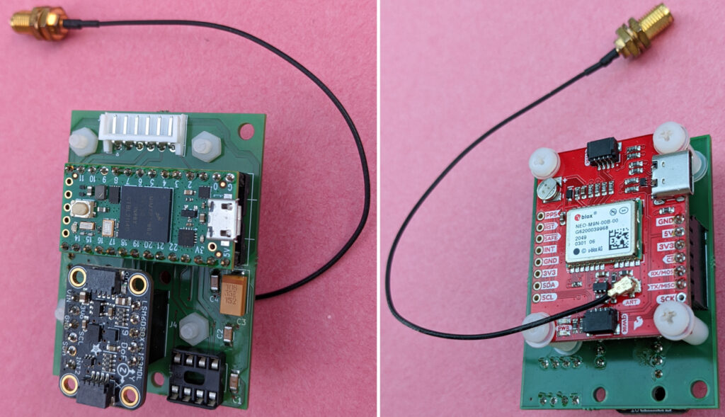
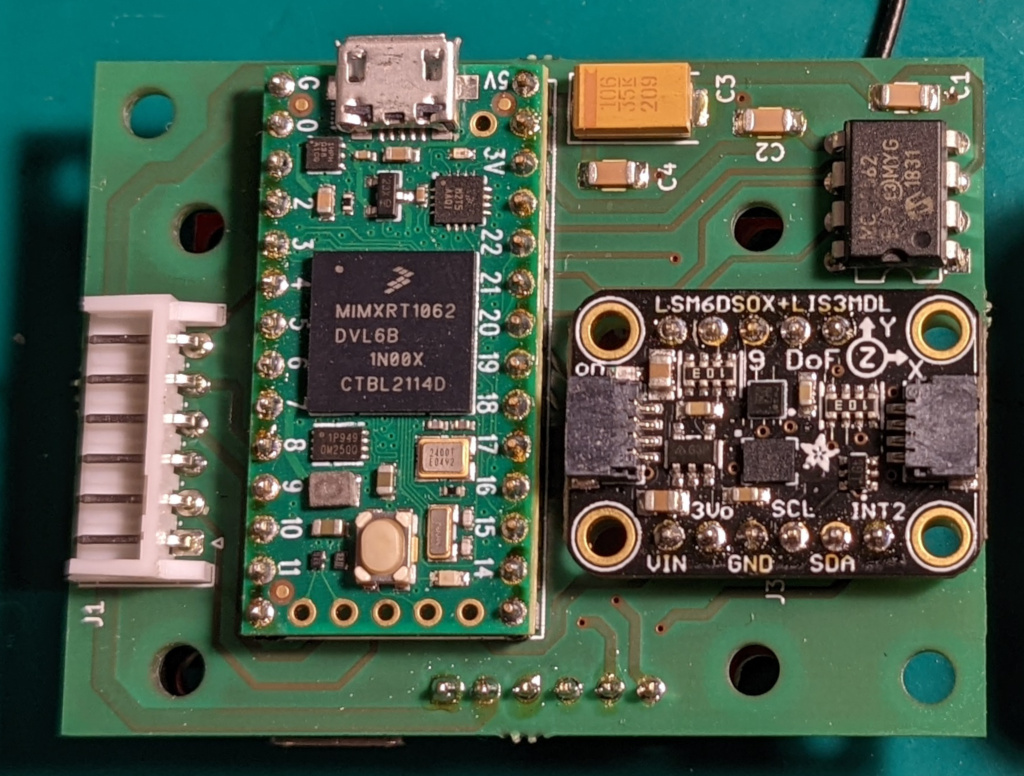
The TheInvenSensee 9DOF MPU9250 inertial unit used in the examples provided with the UNav INS library is obsolete and increasingly difficult to find. In addition, online sales sites are full of clones of dubious provenance that do not work. Therefore, we have adapted the software to use more modern and efficient STMicroelectronics sensors that are very easy to find on the market: the LSM6DSOX (triaxial accelerometer and triaxial gyrometer) and the LIS3MDL (triaxial magnetometer). Both of these sensors are implemented on the Adafruit 4517 breakout board.
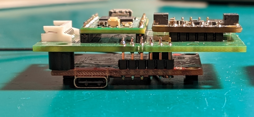
Our AHRS (fig. 2) is built around these sensors, and a U-Blox NEOM9N GNSS mounted on a SparkFun breakout board. The data fusion software runs on a Teensy 4.0 board. To test it quickly with the EFIS already installed in our aircraft, which was designed and programmed for the Naveol AHRS, the output connector is based on the Naveol one with UART serial Rx and Tx pins. A CAN Bus interface (CAN H and CAN L pins) is also provided and can be used with the appropriate software version. See the readme file on GitHub. There is a major advantage of this new AvionicsDuino AHRS compared to the Naveol one: it is an open-source software and hardware system, and everything can be customized.
Installing the AHRS in an airplane
The AHRS must be perfectly aligned with the airplane’s longitudinal and lateral axes during straight and level flight.
The orientation is as follows: Teensy and IMU are on top, GNSS is on the bottom, and the output connector is at the rear.
Results
The first flight tests were particularly satisfactory. The horizon of the AvionicsDuino EFIS with this AHRS follows very closely that of the Dynon EFIS D10A (video 1), as well as the natural horizon (video 2).
It should be noted that the software (EFIS and EMS) used in the videos below are old versions. Many improvements and corrections have been achieved since these videos were made. All the parameters displayed by the EFIS have now been rigorously validated during many other flight tests.
Practical realization
Download the appropriate AHRS software from GitHub.
Version 2.0 or later of this software should only be used with the EFIS_remote_ module software version 2.0 or later and the EFIS software version 3.0 or later. This is due to major modifications to the CAN bus configuration required when removing the UART serial communication line that connected the EFIS to the AHRS and hooking the AHRS up to the CAN bus.
Version 1.3 should be used with EFIS_Remote_Module software V 1.0, EFIS software V 2.5, and a UART serial communication line between AHRS and EFIS. These legacy versions will no longer be updated.
Extract the 3rd party libraries (Bolder Flight Systems) to your Arduino libraries folder.
Download (here and here) and install the Adafruit libraries with the Library Manager of the Arduino IDE.
The U-Blox NEO M9N GNSS receiver needs to be configured with the U-Blox u-center software.
This configuration can be made manually by activating the necessary messages one after the other on the UART1 output. This output must also be correctly configured. This manual setup is an excellent exercise to fully understand how the GNSS works and the u-Blox general “philosophy”.
You can also do this configuration more simply using the downloadable configuration file below. Please note that you must use a configuration file corresponding to the firmware version of your NEO-M9N. See the GNSS Configuration page for instructions on performing automated setup using this file.
The Bolder Flight Systems UBX library parses data from the following messages:
– UBX-NAV-DOP
– UBX-NAV-EOE
– UBX-NAV-POSECEF
– UBX-NAV-PVT
– UBX-NAV-VELECEF
– UBX-NAV-TIMEGPS
All these messages should be enabled on the UART1 output of the GNSS receiver using the u-center software. Baud-rate 921600. The CFG-RATE-MEAS parameter must be set to 50 ms to obtain a message output rate of 20 Hz.
Hi Dan,
Thank you for your kind comment.
Did you try the Teensy 4.x ARM Cortex-M7 at 600 MHz, with 64 & 32 bits float point math unit? It’s very impressive, too!
The u-blox NEO-M9N supports SPI, I2C, and UART. Here, we don’t need the speed of the SPI bus, nor do we need to communicate with several devices. We chose UART for point-to-point communication: it is straightforward to implement, flexible, reliable, easy to debug, and fast. The NEO-M9N GNSS and the Teensy 4.x boards support a 921600 baud rate, which is more than adequate. UART is widely used in communication with GPS receivers.
Benjamin
I have been playing around with a new Adafruit controller board that would likely make this project easier to implement:
Adafruit M4 CAN Express
https://www.adafruit.com/product/4759
It has a built-in CAN transceiver and a Cortex M4, which supports floating point math. So far I’ve been very impressed with it.
Just out of curiosity, is there a reason you chose to use serial communication from the GPS unit instead of I2C? Does the uBlox GPS not support the full data output over I2C or something like that? Just wondering.
Anyway, awesome project! Thanks for sharing.
Hello Kirk Zhang,
If you are using the latest software versions, the AHRS and the EFIS connection uses the CAN Bus. You must, therefore, connect the CAN L (6) and CAN H (2) pins of the AHRS connector J1 with the CAN L (4) and CAN H (3) pins of the EFIS connector J3 (CAN Bus). This connection requires the use of a twisted pair. Unlike a UART connection, you must not cross the wires: connect CAN L with CAN L and CAN H with CAN H.
The EFIS can provide the AHRS power supply. To do this, you must connect the GND and +5V pins of the EFIS connector J3 with the corresponding pins of the AHRS connector J1. A common ground is mandatory anyway.
Benjamin
This project is so interesting that I have been spending weeks to reimplement this great work.
I can’t make clear how to connect the AHRS board to EFIS, is port J1 on AHRS board connected to EFIS board? I’m wondering which port on EFIS board to be connected, can you instruct me the setup?
Hello TingYun,
This is the standard behavior of a non-moving GPS. There is always some error when computing your position. You may not notice it when you are moving because GPS engines use advanced techniques to smooth it. However, when you are standing still, you will see them as moving positions, generally inside a circle of less than 10 or 20 meters, depending on the number of satellites in view. This explains the constant changes observed in the TRK field when the speed is zero.
Benjamin
Encountered a special situation
According to the GPS debugging process, but the TRK of the GPS keeps rotating.
20240708
Hello Benjamin,
Thank you for the reply and help. I finally realized that my library did not contain the proper .h items as you suggested.
I also made the mistake of ordering 3 teensy 4.1’s instead of one 4.0. So that’s now on order as well. I also missed that the magnetometer/compass and temp needed it’s own PCB, so back to Park I go to have that done…. 🙂 So many little things to capture, worst thing, it’s all here on these pages if one looks closely enough… 😉
I’m attempting to get this working for this month so it can go into my panel before end of summer. Problem in Canada is getting everything here and not having to pay double the cost going across the border
Hello Elton,
HorizArt.h is part of the EFIS program, not the AHRS one. You don’t need HorizArt.h for the AHRS.
To compile the EFIS program, you must put all its files in the same folder as the EFIS_AvionicsDuino_V3.01.ino file. This folder must be named EFIS_AvionicsDuino_V3.01
Benjamin
I keep getting a compile error “HorizArt.h not found”. Has anyone else seen this issue pop up?
Cheers,
Elton
Thanks, Dave, for confirming that you no longer have compilation errors.
Teensyduino version 1.59 Beta#3 also solves the issue with TeensyTimerTool 1.4.1
Below are the versions of the libraries used by the AHRS program with my current configuration: Windows 10, Arduino IDE 1.8.19, and Teensyduino 1.59 Beta#3.
uNavINS-master, Eigen-main version 3.0.2, ublox-main version 6.0.6, Adafruit_LSM6DS-master version 4.7.2, Adafruit_BusIO-master version 1.14.5, Adafruit_Sensor-master version 1.1.14, Adafruit_LIS3MDL-master version 1.2.3, TeensyTimerTool version 1.4.1
No compilation issues with this configuration.
I hope Teensyduino 1.59 will be officially released soon.
Benjamin
Benjamin: Thanks for solving that problem!
Yes, Teensyduino 1.57 solves the compile errors issue.
Also, do not use the current version of TeensyTimerTool, 1.4.1 as it will error out. I use version 1.3.1.
Hello Alex,
I think I found the solution to the compilation problems you encountered. With Teensyduino 1.57, the program compiled well on my PC, but when I recently updated to version 1.58, I had the same problems as you. When reverting to version 1.57, everything was working fine again. So I described the issue on the PJRC forum, and Paul Stoffregen advised me to try version 1.59 Beta#3, which immediately resolved the problem. There is, therefore, a bug in Teensuduino 1.58, which prevents the Eigen library from compiling.
If you do not want to install a beta version, you can go back to V 1.57.
Benjamin
Hi Alex,
It is not possible to copy the extract from your verbose compilation log here, because it is almost 150 lines long…
I had to delete it from your message, and move it here. So other readers can read it if they wish.
Your errors all come from the Eigen library, but I don’t understand the causes. A conflict between libraries is most likely. Everything compiles normally on my Windows 10 configuration.
I already gave you some advice last July. Have you tried a complete reinstallation of the Arduino IDE, Teensyduino and the necessary libraries listed (and downloadable) in my post yesterday?
Have you uploaded the HEX file to your Teensy board with the Teensy loader? This file avoids the compilation step, and it works like a charm on my AHRS.
But this HEX file is intended for the AHRS Teensy 4.0 board, and it seems that you are using a Teensy 4.1 board… The INO program, however, compiles perfectly well on a Teensy 4.1.
Benjamin
I am using a Teensy 4.1 with all the LSM6DSOX, LIS3MDL, and NEO M9N and I cannot get the code to compile. I am getting these error messages :
Alex,
Here are the libraries. Be careful to delete any other copies from your computer before installing these libraries. Duplicated libraries in different versions are a common cause of compilation errors.
Benjamin
Hi Alex,
Please find the compiled HEX file of the AHRS program here, so you can program the Teensy 4.0 board via the Teensy loader, without having to compile the .ino file.
Benjamin
I suspect that the AHRS code does not compile due to the fact that old versions of the libraries are used. Could you download them from your computer and send them to me?
Hello. My code for AHRS does not compile. Can you send me the Bin of the firmware file?
Hi Dave,
You are right. DRDY, IntM, and Int1 lines are not used. Before testing the AHRS in real conditions (in flight), I was not absolutely sure that it would work properly. So, by way of precaution, I connected these lines for potential future use. And it turns out they’re useless.
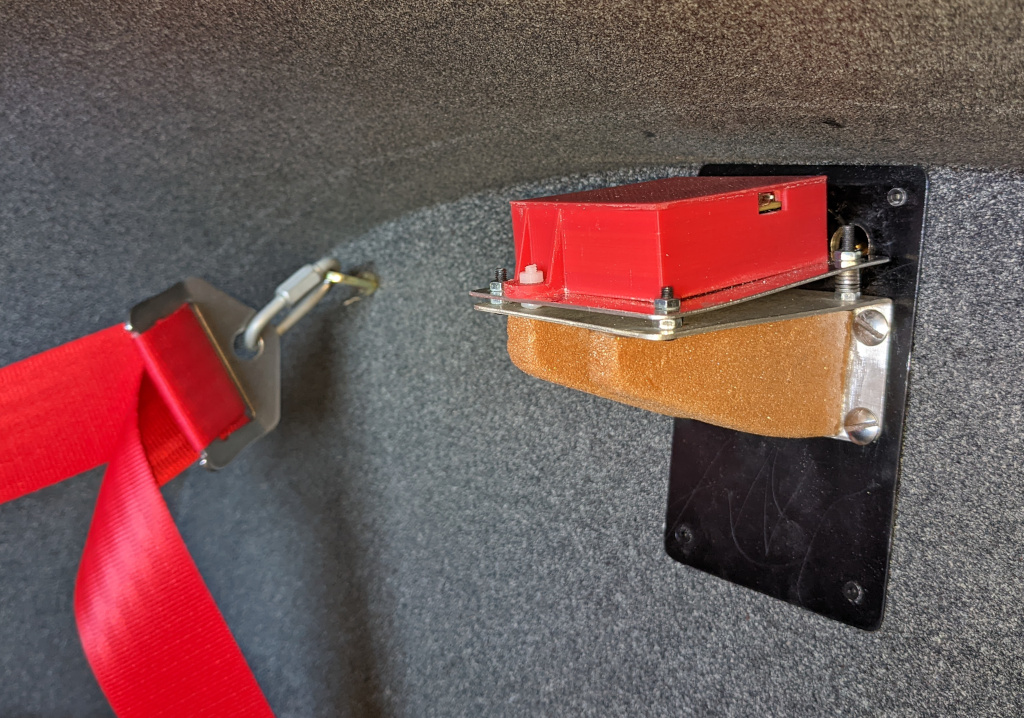
The Adafruit IMU board’s orientation and the AHRS’s location in the aircraft dictated the layout of each element on the PCB. The AHRS is visible at the top and the extreme rear of the cockpit, so it is as far as possible from magnetic interference. This precaution is probably unnecessary due to the very weak coupling of the magnetometer data in the fusion algorithm. This magnetometer does not even need to be calibrated for the AHRS to work perfectly.
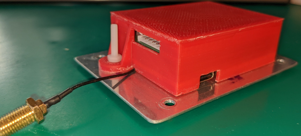
Furthermore, I wanted the connector to be on the back side of the enclosure so the cables were hidden. And I wanted the USB connectors of the GNSS and the Teensy board to be accessible on each side for possible in situ updates of the firmware or the configuration parameters of the GNSS. In particular, to be able to later use the CAN bus instead of a UART transmission.
So there weren’t many options for PCB trace routing and which pins to use. But now that many uncertainties are removed, plenty of customization options exist. Congratulations on your achievement with an LCD display. Have you tested it in flight?
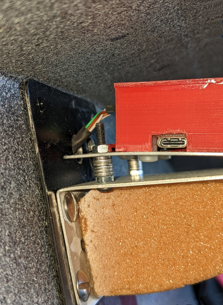
See below some pictures of my installation. Given the above, it would have been simpler to place the AHRS, for example, under the pilot seat…
Benjamin
AHRS PCB
AHRS PCB
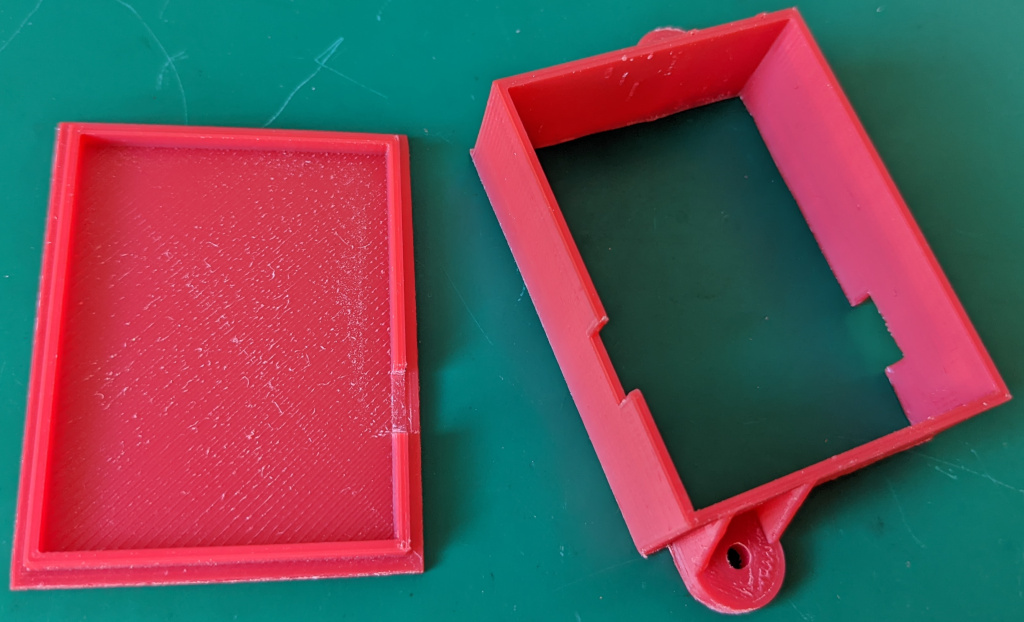
3D printed enclosure
Enclosure on its orientable plate
At its location within the aircraft. Left side, Teensy USB
Right side, GNSS USB
I wanted to add an LCD display to the code so I hooked it up to the I2C lines but it didn’t work. Looking at your code and schematic I see that you didn’t use the default I2C lines (SDA0,SCL0) but rather the SDA1 and SCL1 lines and in the code use &Wire1 reference.
Many I2C device driver code cannot use alternate lines. My LCD was as such.
I deleted the &Wire1 in the initialization of the ADA4517 devices, changed the I2C lines to use the default lines (Pins 18&19) and while the circuit schematic shows the ADA4517 wired with DRDY, IntM and Int1 I don’t see any code that uses them (and the wiring comments in the code does not show them) so I removed them as they were connected to the IC2 default pins.
Everything works now, including my LCD display. Was there some purpose to using the 3 lines that I mentioned? Maybe future used (if needed)?I know what they can be used for but you already have INT2 used for Gyro/Accel interrupt.
Hi Alex,
I understand your compile problem, as I too have it. It most likely has something to do with a later version of a library. I can get a clean compile on an older computer that has many lib’s but not on a new computer (both WIN10, IDE 1.8.19) that I just built and has just a few (newest version) library’s.
I will try to see which library is different between the two computers.
Hi Alex,
Sorry for the long response time. I’m away from home.
I don’t understand why you are getting this error message.
I’m using Windows 10, Arduino IDE 1.8.19 with Teensyduino 1.57. The IDE and Teensyduino were installed with the default options offered by the installer. My personal libraries are also installed in the default folder (on Windows, it should be Documents\Arduino\libraries). I have no compilation errors. The most likely cause of your compilation error is a non-standard installation of the IDE, Teensyduino, or personal libraries. Or a duplicate libraries problem. You might try uninstalling the IDE and Teensyduino, then reinstalling everything and accepting all the default install options.
Unfortunately, I cannot help you with an installation under Linux or Mac (in your previous message, it looks like you are using Windows), nor with the Arduino IDE version 2.xx, which I do not use yet (I actually tried version 2 a few months ago but reverted to version 1 while waiting for the stabilization and bugfix period to end).
Benjamin
I have installed all required libraries and board support. But I am getting an error when I try to compile the code.
In file included from /private/var/folders/8g/tg4chlgj1ybftlz85d3xmgc00000gn/T/AppTranslocation/9D7CAF09-47C9-441D-B026-678FA175026F/d/Teensyduino.app/Contents/Java/hardware/teensy/avr/cores/teensy4/WProgram.h:46,
from /var/folders/8g/tg4chlgj1ybftlz85d3xmgc00000gn/T/arduino_build_163420/pch/Arduino.h:6:
/private/var/folders/8g/tg4chlgj1ybftlz85d3xmgc00000gn/T/AppTranslocation/9D7CAF09-47C9-441D-B026-678FA175026F/d/Teensyduino.app/Contents/Java/hardware/teensy/avr/cores/teensy4/wiring.h:164:17: error: expected unqualified-id before ‘{‘ token
164 | #define abs(x) ({ \
Hi Alex,
Please see this link from Adafruit. And this one as well.
The Adafruit LIS3MDL and LSM6DS libraries have two dependencies: the Adafruit BusIO and Adafruit Unified Sensor libraries must be installed on your PC.
Your compilation error is explained in this line :
c:\Users\Alex\Documents\Arduino\libraries\Adafruit_LSM6DS-master/Adafruit_LSM6DS.h:18:10: fatal error: Adafruit_BusIO_Register.h: No such file or directory
If you open the Adafruit_LSM6DS.h file in a text editor, you will see that line 18 is:
#include "Adafruit_BusIO_Register.h"So compilation cannot complete because you do not have installed the required dependencies.
Benjamin
I am getting an error after everything is set up and trying to upload the code to the board
In file included from c:\Users\Alex\Documents\Arduino\libraries\Adafruit_LSM6DS-master/Adafruit_LSM6DSOX.h:21,
from C:\Users\Alex\Downloads\EFIS-AHRS-AvionicsDuino-main\EFIS-AHRS-AvionicsDuino-main\AHRS_AvionicsDuino_V1.2\AHRS_AvionicsDuino_V1.2.ino:107:
c:\Users\Alex\Documents\Arduino\libraries\Adafruit_LSM6DS-master/Adafruit_LSM6DS.h:18:10: fatal error: Adafruit_BusIO_Register.h: No such file or directory
18 | #include
| ^~~~~~~~~~~~~~~~~~~~~~~~~~~
compilation terminated.
exit status 1
Compilation error: exit status 1
Hi Alex,
I don’t really understand your request. All the elements necessary to build this AHRS are available for download. There are direct links on the AvionicsDuino website for Kicad, Gerber, and drill files. And links to our GitHub repository for software, including all necessary libraries (file Libraries.zip in the 3rdPartyLib tab). You can use any recent version of the Arduino IDE and of course, the Teensyduino add-on.
Benjamin
I’m trying to put together a project. Some videos are not enough and when you try to assemble it, it swears at the lack of libraries. Could you send me the current code and libraries and tell me what version of the Arduino ide. I would be grateful if you can send the archive to the mail 6104023@gmail.com
Sorry Benjamin. Double posted asking for the BOM.
I did see that there were only a very few components on the AHRS board. I wasnt sure if I was to find the info on the EFIS BOM. I’ll dig in and see what I can find. Thanks again. Bonne Nuit.
Great work Benjamin. Very impressive. Do you have BOM for the AHRS?
Hi Tim,
There is currently no BOM for the AHRS due to the minimal number of components: apart from the Teensy board, the GNSS, and the IMU, there are only two decoupling capacitors and the CAN Transceiver. You can easily find precise references and a supplier for these components on the EFIS or EMS BOMs.
Benjamin
Is there a BOM for this project? Amazing work.
Hi Alex,
Sorry for that non-working link, and thank you for pointing it out to me. This has now been fixed.
I invite you to carefully read all these instructions about setting up the GNSS, as this can be tricky.
Benjamin
Hello, the link for setting up the GPS does not work. I’m trying to compensate the project for the board that you indicated, but the data from the gps does not come.
Hi Sandro,
The 4AMP CAR SUPPLY / SWITCH from Mausberry circuits seems very promising. Let us know when you have tested it.
We did some tests with an R-PI running a Processing-based EFIS application and an HDMI display before switching to Teensy 4.1 with a RA8875 graphic controller for simplicity, reliability, sunlight readability, and cost reasons. But this does not allow to make such beautiful and sophisticated graphics.
For your AHRS, I may not have understood well. Does the EKF filter run on the R-Pi or on your STM32-made custom board? In both cases, the software adaptation from the Arduino-Teensy ecosystem to the STM32/R-Pi world can be pretty tricky!
Benjamin, sorry for the late answer but I did some testing in the past weeks. Let’s start from your request: the best way to power the Rpi I found is this: https://www.mausberrycircuits.com/collections/car-power-supply-switches/products/4amp-car-supply-switch
I’m waiting the item
Then: horizon tests was unsuccessful :(, I found some bugs in my code, I’m solving that right now to be able to have another test session next week.
This https://www.youtube.com/watch?v=STQLDmXkwfU is a landing video from my last test flight, as you can see the horizon has some issues (and sometimes it fluctuate and became unstable (basically because internal ahrs angles become NaN)
I’m trying to fix this but it will not be simple. I’m also changing the sensor with a modern 9-DoF LSM9DS1
Some more improvement are coming (like Skydemon side by side)
Keith,
Thank you for your comment.
Drift compensation is not the only issue; fixed-wing aircraft flight mechanics is another. An aircraft is submitted to gravity and centrifugal force during a coordinated turn. Regardless of the data fusion software, a 9DOF IMU alone cannot distinguish between inertial and non-inertial forces.
A great explanation here and there.
Benjamin
Benjamin,
Forgive my ignorance – I am completely new to this subject, and am researching low cost avionics for a client in the experimental realm. I am a mechanical engineer, and coding is not my thing. I found this older post on an open-source AHRS algorithm. Is this type of code what you were referring to as being unsuitable for fixed-wing? It seems that this code incorporates drift compensation without using GPS. What am I’m I missing here?
https://x-io.co.uk/open-source-imu-and-ahrs-algorithms/
Again, I’ve only been looking at this for the past week, so forgive me if I’m asking a redundant question.
Thanks,
Keith
Hi Bob,
I don’t know either if all systems are equally affected by military jamming.
I am far from having the necessary skills to answer your question about comparing the different types of filters!
I was thrilled to be able to use the EKF-based data fusion algorithm developed by the University of Minnesota!
Benjamin
ok thanks for the explanation Benjamin. In the US GPS jamming by the military is a concern. I dont know if the other constellation signals are also jammed.
Have you done any comparisons between EKF and Madgwick filters? Do they basically do the same thing?
Hi Bob,
If only the GPS signal is lost, nothing will happen, thanks to the multi-constellation GNSS.
Suppose all GNSS signals are lost (an exceptional event, excluding antenna disconnection, war, or GNSS interference testing performed by military organizations that are announced via NOTAM); yes, in that case, in a fixed-wing aircraft, you will observe a rapid drift at the first turn.
Benjamin
What happens when GPS signal is lost? Drift?
Hi Sandro,
Thanks for this clarification about powering the RPi. What about that solution?
Did you eventually find a sunlight readable HDMI display for the Rpi?
My Riverdi IPS display is perfectly sunlight readable (1000 cd/m²), however, it is not HDMI, and hence incompatible with the RPI.
Ahhh, good, we are looking at the same issues to find solutions.
Currently I’m powering the RPI with a more configurable power hat X708, I use it as main power source for the EFIS subsystem (EMS/Rpi/Display). My goal is have the EFIS circuit virtually independent by the main plane power bus. This will not be my final setup, it’s good for testing but, at the end of the day, makes the backup power solution too complex to be managed.
After some investigation and field testing I just need a tablet-like backup battery (~5-10Ah, <1Kg) with a 12v output to power up my EFIS bus. With a common size tablet backup battery I should be able to power the full system for 30-60mins. The hard thing is to ensure it's a LifePO battery and not a LiPo (I don't like fire in my plane, smoke only is a little bit better).
The other solution I'm going to test is to power up all the system by the backup battery and connect the backup battery to a simple USB converter. This one is for sure a simpler solution but I need to find a smart battery that will allow me to get direct power from the USB charger when available.
All the other solution I investigated are not safe in my opinion (like double plane battery with circuit split) or commonly available Rpi UPS.
Thanks to my EMS configuration I'm monitoring the generator and battery voltage (amps too) so I will be able to detect a power loss and I'm pretty sure I could guess the cause by merging GPS/airspeed/RPM and power status. In this way will be simple to implement an automatic shutdown of the system when the plane is still on the ground and not shutdown the system while I'm managing an emergency in flight.
Ah, I'm really interested about your display. How is the visibility in direct sunlight and at sunset? I'm using a cheap but sunlight readable one but I'm looking for a second one a little bit better.
Hi Sandro,
Thank you for your comments and for sharing your ambitious project!
Do you have any specific recommendations for a strategy to secure the Raspberry Pi power supply in the event of an unexpected power loss? Such as inadvertently switching off the master switch at the end of a flight prior to safely shutting down the R-Pi…
Let us know about your future flight tests with the AHRS!
Hi Benjamin,
thanks for your reply and for the link. I found the issue, it’s related to my setup using arduino on STM32F4, a line in the uNAVIns.cpp needs to be changed from:
_dt = (float)_t;
to:
_dt = (float)_t/1000000.0;
Now it seems working.
Anyway let me share my setup:
I’m using a custom made board as EMS (STM32F4) to collect all the engine data with some ADC (ADS1115) + Canbus (MCP2521) + EGTs sensors + AirData/Barometric sensors + MPU9250 (will be changed in the future with a newer one) and some other stuff on it.
My board has NO GPS installed, it was too expensive when I started and now it costs much more.
On the other side I build an EFIS based on Rapsberry Pi running android Lineage OS 19 (with some custom mods) with USB canbus and GPS (usb ublox clone). The EFIS UI Interface is Web-Based and it could be simply moved to a different platform without big issue.
I choose this setup because I want a single screen for EMS/EFIS, SkyDemon, Audio, Meteo (Windy), VHF-COM, XPDR, Google Earth, etc and not as complicated as a Dynon panel but simple like an android tablet with my apps installed on it.
The EFIS Web Interface is running all the high level logic except for the AHRS and, after I found your excellent article, I added some code to communicate back to the EMS the GPS data at ~3Hz so the Filter can use these data to calculate the right attitude with your wonderful Filter code.
First couple of flights was really helpful but I saw the “wrong indicated bank” issue at first coordinated turn :(.
Now I will test deeper the filters with the new GPS data and I plan to have a flight on the next weekend
Hi Sandro,
There has been a great deal of discussion concerning this nan-nan-nan issue on the PJRC forum. But I personally never encountered this problem. Neither with the MPU9250 nor with the LSM6DSOX/LIS3MDL. Be careful with axes; they are not the same between Invensense and ST sensors! AHRS AvionicsDuino V1 software is intended for ST sensors. If you use it with MPU9250, the axes need to be corrected.
Which GNSS do you use? And which libraries?
Hello,
I’m trying to setup a basic env to run the AvionicsDuino V1 software. My current board is mounting a MPU9250 but I receive also GPS data with a custom freq.
With a simple env with GPS returning no motion, fixed altitude and MPU9250 on a desk I see the filter returning NAN after few cycles in the best cases (I tried any board position):
Acc: 1.71 0.64 8.72
Gyro: 0.03 0.01 0.01
Mag: 44.78 -13.53 -63.28
Pitch/Roll/Yaw: 10.04 3.78 0.00
Acc: 1.70 0.62 8.70
Gyro: 0.02 0.01 0.01
Mag: 45.84 -13.18 -64.65
Pitch/Roll/Yaw: -61.95 -135.63 111.29
Acc: 1.70 0.63 8.69
Gyro: 0.02 0.01 0.01
Mag: 45.13 -15.31 -65.33
Pitch/Roll/Yaw: 21.95 18.93 -77.54
Acc: 1.70 0.63 8.70
Gyro: 0.03 0.01 0.01
Mag: 44.78 -14.24 -64.65
Pitch/Roll/Yaw: nan nan nan
Acc: 1.71 0.63 8.70
Gyro: 0.03 0.01 0.01
Mag: 44.96 -12.64 -63.79
Pitch/Roll/Yaw: nan nan nan
I don’t get what am I missing. Any help would be appreciated
Hi Marcello,
The Dynon EFIS needs to be connected either to the circuits of static AND dynamic pressures in order to be able to calculate the airspeed of the aircraft, or to a GPS/GNSS , at the best to both.
With the Naveol AHRS, without air data, depending solely on a GPS signal could be a “problem” in extremely rare situations. With a multi constellation GNSS (GPS, Glonass, Galileo, Beidou), such a situation is even more highly unlikely. Furthermore, remember that this system is not intended to IMC flight !
Benjamin
Hi,
I am looking to build an EFIS a long time and this AHRS problem I do not got solve. It’s great option this Naveol, congrats!!! Even thouth the better way is not depending on GPS signal, maybe this can cause problems.
I am intrigued about Dynon EFIS, I guess the Dynon AHRS unit does not need GPS signal.
Waiting for your updates 😉
Hi Daniel,
I knew the very interesting page of Jiří PITTNER, and I look forward to seeing the flight test results with his system. I did not succeed adapting his code to our hardware.
I did not know the Homebuiltavionics website. This system seems firmly targeted at a professional audience. Very expensive and sophisticated components.
As someone wrote on the Vans forum : “Eagerly awaiting the day one could duplicate this on another aircraft.” Unfortunately Ebbe (the pseudo of the homebuiltavionics webmaster on the Vans forum) wrote on this same forum : “sorry, no complete software will be posted for now”. No schematics available either…
Yet it is fairly easy to build a simple, reliable and inexpensive AHRS suitable for non-certified aviation. IMUs and GPS can be found everywhere for a few euros or dollars. The problem is the fusion software which absolutely has to take into account the speed and flight mechanics of fixed-wing aircraft. AHRS algorithms intended for land vehicles or quadcopter drones are not suitable.
So if you manage to create such an AHRS and if you agree to share the code and the hardware, we would be very interested!
Actually, for the moment, the Naveol system gives us complete satisfaction, but it is not an open system.
Benjamin
Indeed, the Ardupilot-project seems quite confusing.
These two webpages you will probably know too:
http://homebuiltavionics.com (one of the most outstanding projects I have seen so far)
– unfortunately no code available, also not the “cheapest” sensors used as far as I have seen
https://www.pittnerovi.com/jiri/hobby/electronics/avionics/index.html
If I find time I will try to build such a system and inform you.
Hi Daniel,
Thank you for your comments.
Of course we are aware of Ardupilot. It is indeed a very sophisticated project. However, the drawback is that it is a real labyrinth, dedicated to flight controllers for UAVs, for autonomous flight or controlled flight from a ground station. The hardware is not so open, peripherals are innumerable, and countless software programs form an almost impenetrable jungle. For an EFIS a lot of this is unnecessary, all we need is a simple AHRS, powered by some MEMS and a speed sensor (GPS or airspeed), and capable of providing the Euler angles that describe the position of a fixed wings real aircraft. As indicated on the page, MEMS alone are insufficient for fixed wings aircrafts, the integration of the speed in the calculations is essential.
Hardware is simple, but fusion software is a complex issue. We have not been able to create such a software and we did mot find any satisfactory open source solution over Internet, including on the ArduPilot website. As we are neither engineers nor mathematicians, we asked for help from the Naveol company which provided us with a very simple, cheap and effective AHRS. However, any help to make an open source open hardware one by ourselves is welcome! The AHRS is really the key component of an EFIS.
Congratulations for your web pages!
Benjamin
Hello, very interesting webpage.
I am also interested in AHRS development and I am wondering if it is indeed impossible in a “cheaper” way – as you say.
For example:
Did you have a look at Ardupilot – Arduplane? To me, this seems to be the most sophisticated project in at least UAV controlling.
The IMU sensor hardware is typically based on cheap MEMS-sensors.
They seem to use an 22 states EKF (extended kalman filter) for sensor fusion.
https://github.com/priseborough/InertialNav/blob/master/derivations/GenerateEquations22states.m
https://github.com/ArduPilot/ardupilot/blob/master/libraries/AP_AHRS/AP_AHRS.cpp
https://github.com/ArduPilot/ardupilot/tree/master/libraries/AP_NavEKF3
https://github.com/ArduPilot/ardupilot/blob/master/libraries/AP_NavEKF3/AP_NavEKF3_AirDataFusion.cpp
I am an electrical engineer and I am building a relatively cheap radio altimeter in the 4.3GHZ-frequency range as well as 24GHz-frequency range, you can have a look on my webpage(s) – prototype development:
https://radio-altimeter.dit24.com/prototype/
for German users (Radar Altimeter):
https://radar-altimeter.smarter-tech.de/prototypenentwicklung/
Hi Robin,
Thank you for the comment.
Currently, this AHRS module is not yet marketed by Naveol. This is a prototype that allowed us to validate the design of the EFIS. At the present time, there are already 10 people interested, Naveol would like at least twenty potential customers to finalize a commercial version. I hope we reach that threshold in the next few months.
The firmware of this AHRS is not open source, it belongs to Naveol. To my knowledge, there is currently no open source software capable of animating an AHRS usable in a fixed-wing aircraft…
We now have a new version of our EFIS, which is being flight tested. Results of these tests will soon be published on AvionicsDuino, as well as Kicad files and a bill of materials (BOM), so, if you are interested, it wil be easy to build this new version, which includes a GPS. I hope Naveol AHRS will soon be commercially available, because it’s really a great and cheap thing compared to other commercial AHRS.
At present, a new EMS is also being flight tested. So several new articles very soon on AvionicsDuino!
Hi
the past day’s i have been going trough your website, and i would like to build the efis, with the information givin it seem pretty straigh forward to build the screen besides “which provided us with a prototype based on a modified version of its AHRS NavH 2.0,” So as i understand this is not something that we can build as it comes specially build from the manufacturer ?