(Arduino Micro-EMS: Last updated by Benjamin on April 17, 2023)
A new version of the Micro-EMS, based on a Teensy 4.0 board, is now available.
EMS (Engine Monitoring System) is the device that monitors engine operation. It centralizes information from all sensors and displays the results in real time on a screen. The parameters usually monitored on a single-engine piston light aircraft are RPM, oil pressure and temperature, cylinder head and exhaust gas temperatures, fuel flow, and level, inlet pressure, voltage and amperage in the electrical circuit.
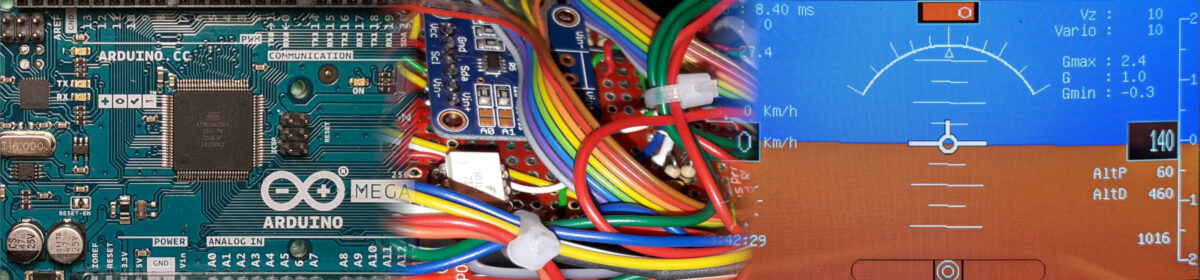
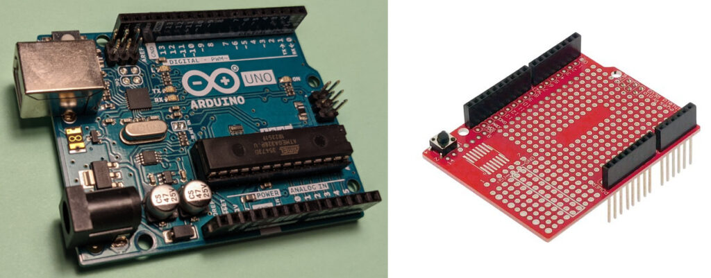
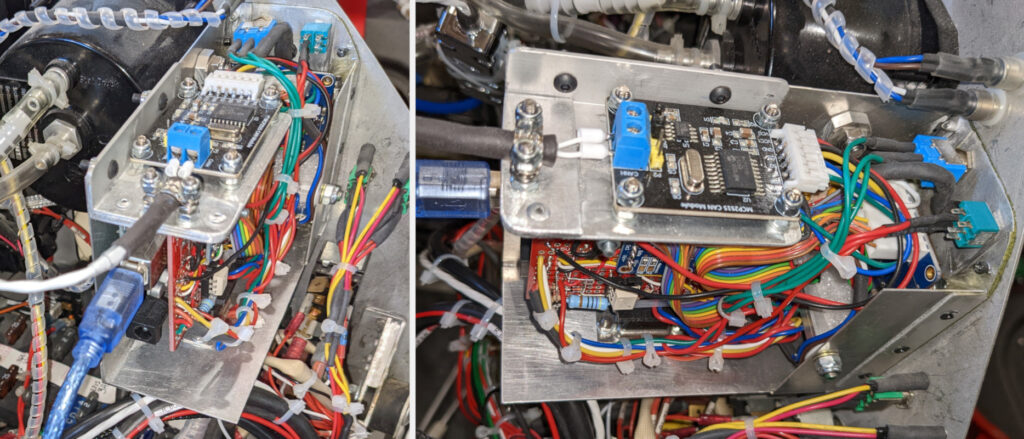
The micro-EMS shown here is based on an Arduino Uno board. Why Micro-EMS? Because apart from its small size, it only monitors a small number of the parameters mentioned above, namely RPM, fuel flow and level, and main bus voltage. In the first version of this Micro-EMS, charging/discharging battery current was also monitored, but the main EMS now provides this function much more efficiently. The monitored parameters are transmitted to the main EMS over the CAN Bus; this functionality was added to the second and current version.
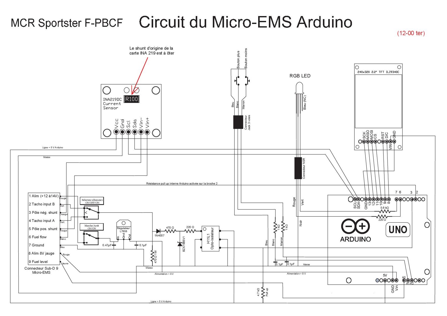
The aircraft on which this Micro-EMS is mounted is powered by a Rotax 912 80 CV engine, whose original electronic ignition units (Ducati) have been replaced by programmable capacitive modules derived from Ignitech DC-CDI-P2. These ignition units are configured to generate one pulse per revolution on their “Tacho” output towards the tachometer. This output delivers a square signal with a 50% duty cycle and a constant amplitude of 16 volts, whatever the speed.
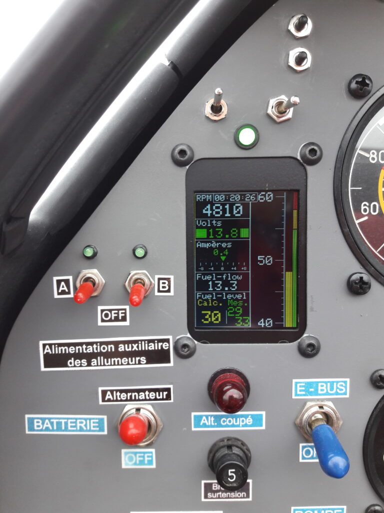
The display uses an Adafruit 2.2″ TFT LCD 240 × 320 color screen; all information is shown on one screen. This economical screen is not “sunlight readable,” but placed under the cap of the dashboard, it is easily readable in flight under all circumstances (fig. 1).
Using many direct manipulations of the ATmega328P registers, the micro-EMS program only works on Arduino Uno, Nano, or compatible boards.
Tachometer function:
The input stage uses a Schmitt trigger optocoupler to pre-process the signal from the Tacho-output of the ignition units. With this same input stage, the system could just as easily exploit the signal delivered by the native sensor of the Rotax engine.
The signal thus processed is applied to Arduino digital pin 3, then exploited using Timer 1, and the external interrupt Int1.
The program measures the period of the signal and deduces its frequency. Reference here. This is the most effective of the various solutions tested for measuring the period of this type of signal in the frequency range of interest to us. Simple techniques that count the number of pulses during a given interval are unresponsive and inaccurate because the frequency is low. The use of the PulseIn function was also disappointing.
In flight, the difference in the RPM between the micro-EMS and the commercial digital tachometer fitted on the instrument panel never exceeds ten revolutions per minute. A corrective factor for the frequency of the microcontroller must be applied to obtain this precision; see the remarks in the source code of the program.
Ammeter function:
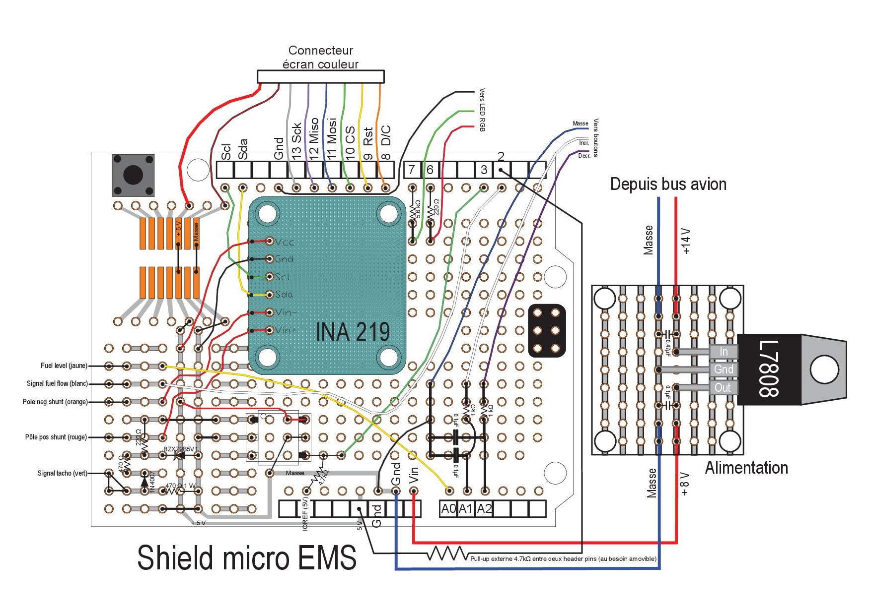
The V1 version of the program displayed the charging or discharging current of the battery, thanks to a digital high-end bidirectional INA219 12-bit voltage amplifier, using the 50 mV / 20A / 0.0025Ω shunt mounted in the electrical circuit during the construction of the aircraft. This was neither precise nor accurate. In the V2 version, this functionality has been removed. Current sensing is now much better implemented in the EMS.
Voltmeter function:
The program continuously displays the voltage via the INA 219. The measurement by the Arduino board itself, via an analog input, and a simple voltage divider, would have been just as effective. But with the INA card, no voltage divider bridge or calibration is necessary.
The displayed voltage never differs more than 0.1 volts from a reference multimeter.
“Idiot Lamp” function:
An RGB LED acts as a “smart Idiot Lamp”: if the bus voltage is above 13.3 V, the LED is green; this is a normal state. If the voltage drops while the engine speed is below a certain threshold, it is solid red; this is also a normal state when the engine is idling. On the other hand, if the voltage drops with a higher engine speed, it flashes (with the help of Timer 2) to better attract attention: a very abnormal situation!
The Arduino UNO (or Nano) still has resources with these first functions. And there is still room on the screen—next step: fuel management.
We want to use the external INT0 interrupt on pin 2 and Timer 0 for the fuel flow. But Timer 0 is already used by the Arduino environment for the delay (), millis (), and micros () functions, and for PWM on pins 5 and 6 … So we have to be cunning; this reference helps! See also the comments in the source code.
Fuel management:
The EEPROM is available to store the fuel level in the tank after the system has been powered off.
PCINT1 and analog pins A1 and A2 are used, with the help of two push-buttons, to adjust the actual fuel level in the tank at the start of the flight, thanks to the PinChangeInterrupt.h library.
The analog pin A0 is used for continuous measurement of the actual fuel level in the tank using the fuel sender. This is a high-resolution WEMA S3 (0 to 190 Ohms) 35 cm resistive probe; its resistance varies from 0 ohms with an empty tank to 190 ohms with a full tank. The 29 reed switches of this probe ensure a very decent resolution. Unlike capacitive probes, this probe is insensitive to the nature of the measured fluid: AVGAS 100LL, MOGAS, or a mixture of the two.
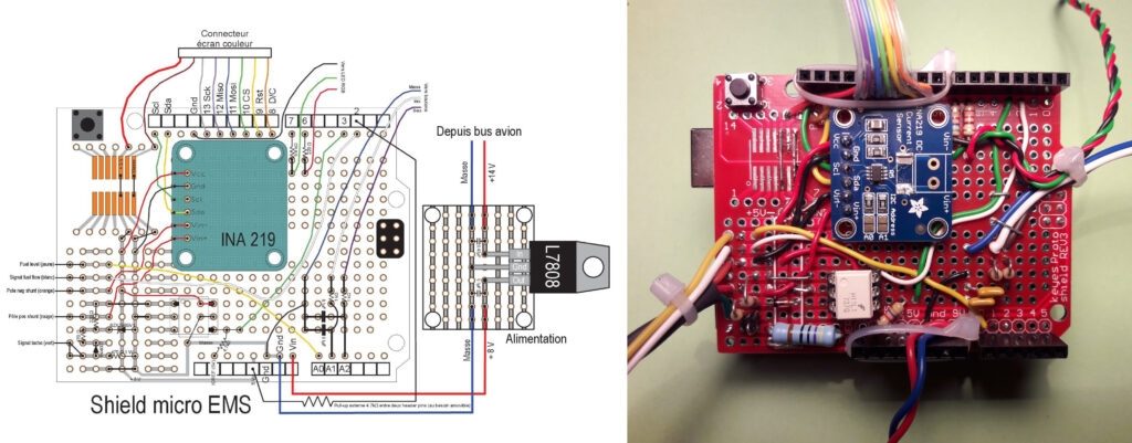
The probe is used in series with a 220 Ohm resistor to form a voltage divider. This resistor is located upstream of the 3-pin connector of the probe so as not to risk toasting the Arduino by distractedly switching on the master switch when the tank has been removed! If this resistor were placed on the ProtoShield, forgetting to reconnect the probe would then apply 8 volts directly to A0. Indeed, the entire Micro-EMS is supplied with 8 volts by an L7808 regulator. A 100µF capacitor has also been placed in this connector to dampen the rapid variations in voltage across the probe related to ripples on the fuel surface.
The fuel flow uses Timer 0, Int 0, and digital pin 2. The “Red Cube” flow sensor (Electronic International FT-60), with a 10kΩ pull-up resistor to 5V, generates a square signal, the pulse width is highly variable, and the signal frequency is highly unstable. Under these conditions, the method employed is to count the pulses during a given time interval, then filter the result to stabilize the flow rate display.
The results obtained with this fuel computer are very satisfactory: the display is stable, and at the end of the flight, even for a prolonged period (up to 4 hours), the remaining fuel levels, either displayed by the computer or measured manually in the tank, never differ by more than one liter. And this level is always in the range of 3 to 4 liters measured by the Wema probe.
Stopwatch
And finally, as the fuel flow sampling is carried out precisely every second by the Timer0, we take the opportunity to add a last additional function to this micro-EMS: the display of the time elapsed since the engine was started. The stopwatch only runs if there is fuel consumption.
CAN Bus
In Micro-EMS V2, a Joy-IT SBC-CAN01 module provides the Arduino Uno board with CAN-Bus capabilities.
Arduino sketch
Most measurements are filtered by a running average method, which ensures excellent display stability/responsiveness. An infinite impulse response filter would be much simpler to implement; this is done in the EFIS program.
All calculations are performed on integers to avoid float variables to the ATMega328 microcontroller, which does not have a floating-point unit.
Two constants must be customized in the program, they appear for convenience at the very start of the program:
- the K factor, depending on the characteristics of the flow sensor used,
- the actual frequency of the Arduino UNO clock because it is not always precisely equal to 16 MHz.
Successive approximations allow for adjusting these two constants during the first flights, which requires a new upload each time. It’s less ergonomic than a rotary encoder coupled with a menu system, but it’s much simpler!
Hi Igor,
I read on the manufacturer’s website that “Electronics in the sender’s head convert capacitance into resistance, voltage, or milliamps, as determined by which output is ordered.”
So I think you could use this sender without any modification of the circuit and with minimal software changes if Centroid Products is able to configure the output as if the sensor was resistive and if this “resistor” can be powered by the 8V output of the circuit. Please see the schematics of the Arduino micro-EMS and its connections to the aircraft circuits, especially the role of the 220 Ohm resistor to form a voltage divider.
Furthermore, if they are able to configure the resistance so that with an empty tank, you read 0 ohms and 190 ohms with a full tank, software adaptations would be minimal (simple calibration). If the output is 240 ohms full and 33 ohms empty, more significant changes in the software would be required.
If the manufacturer is not able to configure a resistive output as described above, you could quite easily adapt the software to a voltage output and only connect this output to pin 9 input of D-SUB connector via an appropriate voltage divider, leaving pin 8 +8V output unconnected. This solution seems actually simpler. Be aware that under no circumstances should a voltage greater than 5 volts be applied to pin 9 of d-SUB connector, as it is directly connected to the analog pin A0 of the Arduino board. If needed, I could help you calculate the voltage divider, make software modifications, and calibrate the sender for your tank.
Perhaps a Centroid Products engineer could help you choose the best output configuration for the sender if you send him a copy of my reply, together with a link to the AvionicsDuino Arduino Micro-EMS page.
Also, be aware that with a capacitive sensor, fuel type (MOGAS or AVGAS) significantly influences the measurement results, unlike a resistive sensor.
Benjamin
Hi!
Could I use this http://www.centroidproducts.com/ fluel level sender with the device
Hello Filipe,
Sorry, I’m not sure I understand the question correctly, but I will try to respond.
I don’t know much about the 912iS, but I know it uses CANAerospace extensively and has been designed from the outset around the specifications of this standard with the help of its designer, Michael Stock.
But unless you are a professional designer of avionics systems and have signed a Non-Disclosure Agreement with Rotax (or use reverse engineering), I doubt whether it would be possible to decode and read the messages exchanged over the 912iS CAN bus, especially within an open-source project like AvionicsDuino.
If the Rotax 912iS used an open format, then yes, it would be straightforward to read the data and display it on any DIY EMS.
Benjamin
Hello John, congratulations for your project and share the information.
I have a 912is which transmits the information via can bus Canaerospace. How easy would be to integrate?
Thanks,
Filipe
Hi John,
Thank you for your kind comment.
You could take a look at the BuyDisplay website. They have a lot of interesting products. For example, this one includes a 4.3″ display and an Arduino shield that provides the appropriate level shifter. If you need a customized product, you can contact them, they are generally quite responsive.
A good option could also be to select a microcontroller with 3.3v logic which facilitates the choice of peripherals. Teensy boards are more powerful, less bulky, and not more expensive; they are very simply programmed with the Arduino IDE.
Benjamin
Hi,
Great site for amateur builders of aircraft. My RV10 will have dual battery and duel bi-directional current sensors (hall effect). I have build the monitoring system using an Arduino Uno (clone) and a CAN bus shield that also provides regulated 5V supply to ardunio. The can Bus data frame sends that Voltage and Current data (after digital filtering) to the cockpit instrument.
I am trying to find a really good screen that can operate on 5V logic levels such as the one used in the EMS. Do you have any suggestions? Oh the other end of the Can Bus is another Can Bus Shield plus Ardunio Uno also with 5V logic.
Hi,
I’m sorry, the link no longer works on the English page. I am far from home, I will correct this anomaly as soon as I’m back, in a few days. In the meantime, you can download the micro-EMS program on the French page of the site, where the link works properlly.
Benjamin
Hello
Source code cannot be downloaded