(EFIS: Last updated by Benjamin on March 25, 2024)
The EFIS or Electronic Flight Instrument System combines the indications of the primary flight instruments, at least the artificial horizon, the ball, the turn indicator, the anemometer, the altimeter, the variometer, and the compass, on a single display. Before the widespread use of EFIS and digital technology on aircraft instrument panels, an individual device was dedicated to each function, generally based on analog, electromechanical, or pneumatic technology.
As an EFIS is first and foremost a computer, the list of other indications or functions that can be implemented is not exhaustive: density altitude, true air speed, angle of attack, outside temperature, G-meter, wind speed and direction, voltmeter, clock, autopilot… etc.
This page will describe the main unit of the AvionicsDuino EFIS. The reader can refer to the AHRS and Digital Compass pages for the description of these modules, which are integral parts of the EFIS.
AvionicsDuino EFIS general presentation
The primary function of the main EFIS unit is to manage the screen (graphical display of the artificial horizon and all textual data) and make many complex calculations to convert raw sensor data into human-readable format useful information for pilots.
For example, compute the aircraft’s speed from static and total pressure measurements. Or calculate the position of the ball based on lateral accelerations. This unit itself contains a very limited number of sensors, namely the two pressure sensors (absolute for static pressure and differential for the Pitot probe) and the inside air temperature sensor.
All other sensors are located in the above-mentioned modules (AHRS and Digital Compass): GNSS, gyrometers, accelerometers, magnetometers, outside air temperature, and relative humidity sensors. Complex computations are also performed in these modules.
EFIS general architecture
It is shown schematically in Figure 1. The main unit is represented in the yellow box, the AHRS in the pink one, and the magnetometer module, with outside air temperature and relative humidity sensors in the green one.
The main unit includes a 5-volt power supply (described elsewhere). This power supply also provides the voltage required by the other two modules (red arrows). It uses one of the two twisted pairs within the CAN Bus Cable.
All modules communicate with each other via the CAN bus (green arrows). In earlier software versions, the AHRS communicated with the EFIS main unit via a serial UART channel, shown in Figure 1 by a two-way dotted blue arrow. This UART serial communication has become obsolete, but the software versions that used it can still be downloaded from GitHub. However, they will no longer evolve and will no longer be updated.
Main components
The heart of the main unit is a PJRC Teensy 4.1 board equipped with an NXP i.MXRT1062 microcontroller (ARM Cortex-M7 @ 600 MHz). See the microcontroller boards page.
The other components are listed below:
- Differential pressure sensor: Analog Microelectronics AMS 5915 0050D to measure the differential pressure between the static port and the Pitot probe and to calculate the speed. The measuring range of this sensor is 0 to 50 hPa, which is suitable for the speed range of the MCR Sportster (0 – 320 km / h).
- Absolute pressure sensor: Analog Microelectronics AMS 5915 1500A to measure static pressure and calculate altitude. The measuring range of this sensor is from 0 to 1500 hPa.
- 1-Wire DS18B20 inside air temperature sensor (IAT).
- Grayhill 62SG optical rotary encoder for menu navigation.
- CAN Bus Transceiver MCP2562EP
- Adafruit RA8875 graphics controller
- 4.3 ″ 480 x 272 TFT LCD display, IPS, 1000 cd / m², Riverdi RVT43HLTFWN00
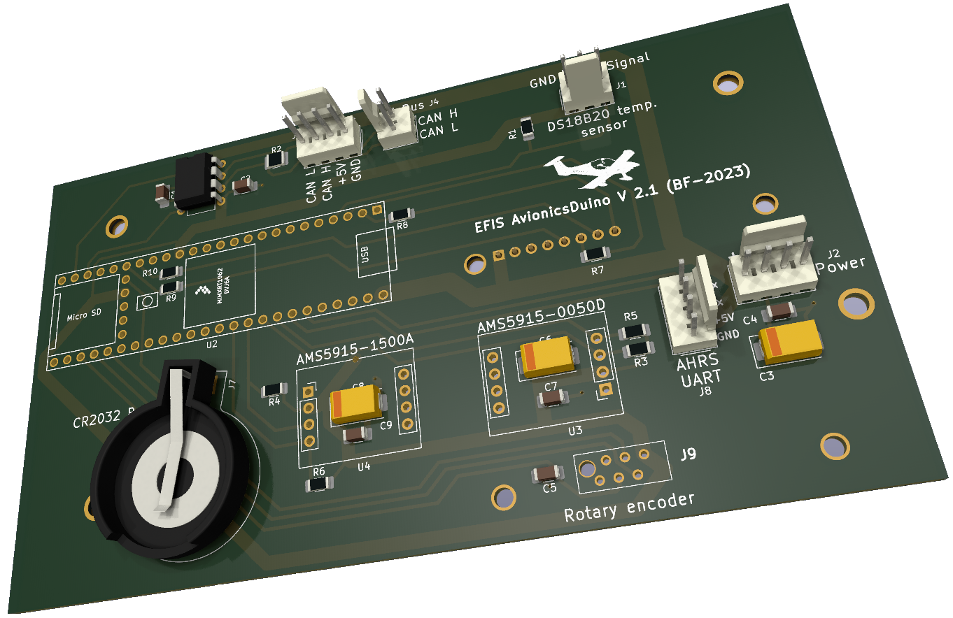
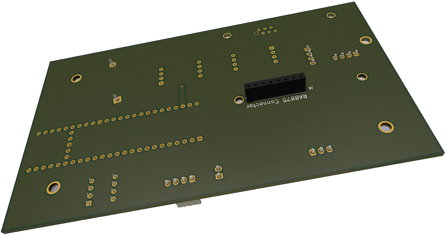
Printed circuit board
Figures 2 and 3 are 3D views of the printed circuit board in its current 2.1 version (views produced using KiCad). Compared to the previous version 2.0, there is little change. The connector for a GNSS has disappeared.
A GNSS was previously incorporated into the EFIS’s central unit, but it is now useless. Indeed, before developing our own AHRS, we used an AHRS prototype provided by the Naveol company. This prototype included a GNSS chip, but its closed software did not allow for full access. Hence, a GNSS needed to be integrated into the central unit. The GNSS included in the AvionicsDuino AHRS now provides all the data required for the EFIS.
The AHRS-UART connector has become unnecessary with the latest software versions. In fact, with these versions, the AHRS sends its data to the CAN bus. Therefore, it is essential to connect the AHRS and the EFIS central unit to the CAN bus.
Circuit diagram
Figure 4 below shows the electrical diagram of the EFIS main unit. KiCad files can be downloaded below.
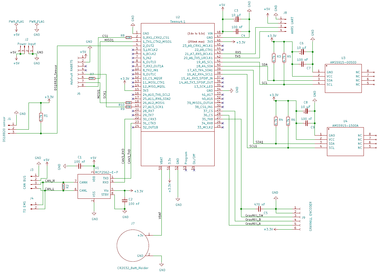
This diagram shows a 120-ohm CAN bus termination resistor (R2). This resistance was justified before the bus extension to the AHRS, which is now the node closest to the bus’s end. Therefore, resistor R2 must be removed from the main EFIS unit, and a 120-ohm resistor must be placed at the AHRS end of the bus (see the CAN bus page).
The J4 connector, entitled “TO EMS,” was intended to connect the EMS to the CAN bus at the same time as the EFIS, in the hypothesis that the EMS and the EFIS would share the same enclosure. Even if such a common connection works well in practice, in strict logic, it is not desirable, so the J4 connector is unnecessary.
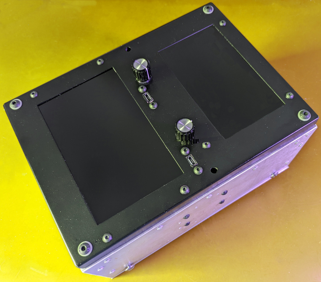
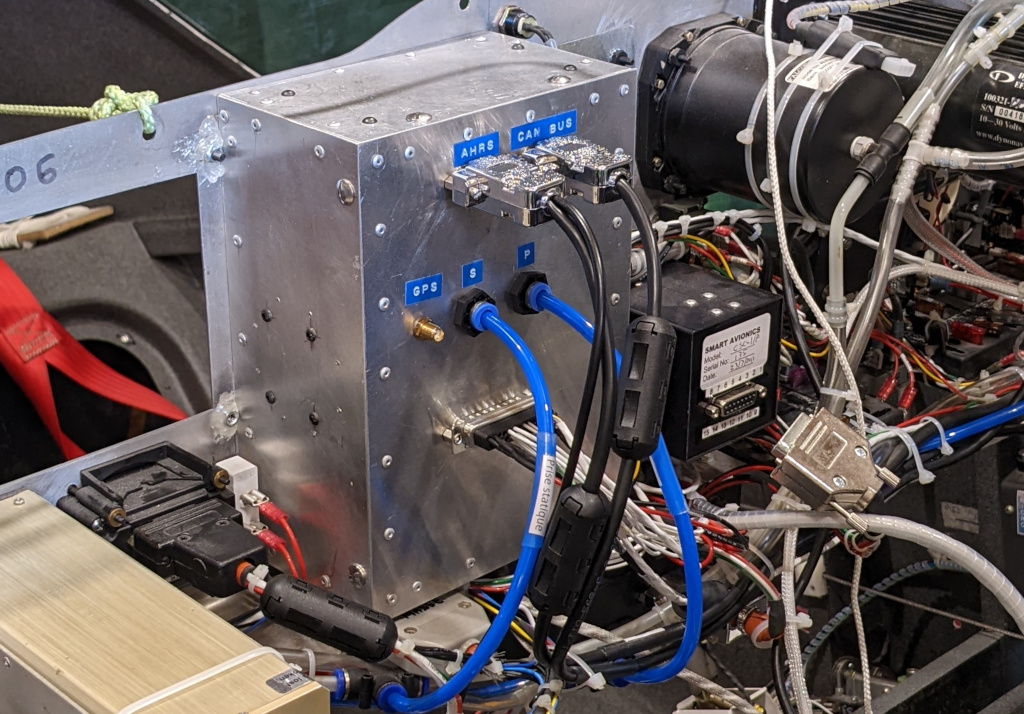
The aluminium enclosure
Figures 5 and 6 show the combined case, which contains the central units of the EFIS and EMS. No plans or instructions are provided on this site for making cases. Indeed, one of the characteristics of homebuilt aircraft is the huge diversity of projects. Instrument panels are highly customized, so a case suitable for one will not suit another. Therefore, we believe it is up to the builder to design its enclosures.
We have chosen to make our cases from aluminum to prevent electromagnetic interference (EMI) and electromagnetic compatibility (EMC) issues. 3D-printed enclosures can also be shielded internally or externally with copper or aluminum adhesive tape. Our cases are made of aluminum sheets and angles assembled by screws and rivets. Note in Figure 6, produced during installation on the panel, that there is still a connector for a GPS antenna. Since then, this connector has been dismantled, and its hole has been sealed… with copper adhesive tape.
Flight test results
For the flight tests, a flight data recorder (FDR) was previously developed to rigorously compare the data from our EFIS with those from a commercial EFIS serving as a reference. This reference was a Dynon EFIS D10A.
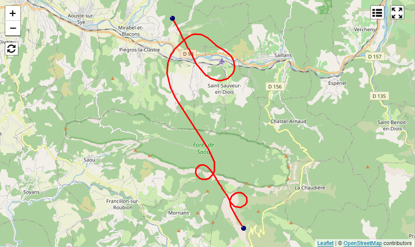
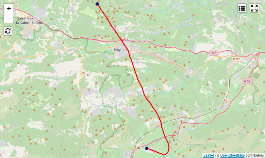
The first COM port of the FDR received the serial output of our EFIS, the second that of the Dynon, and the third the NMEA stream of a u-blox NEO M9N GNSS, allowing a common time-stamping for all the data and the analysis of the GPS tracks.
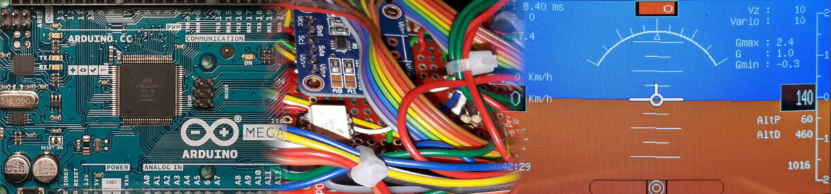
The videos below were made during one of the many test flights carried out to test the EFIS. They demonstrate the excellent performance of the AvionicsDuino AHRS, which is perfectly suited to the flight mechanics of fixed-wing aircraft. The artificial horizon perfectly follows that of the reference EFIS and the natural horizon in a stable and prolonged manner. The position of the ball is identical on both EFIS. The pressure sensors are perfectly suited to this use. The indicated airspeed and altitude are identical to the Dynon’s.
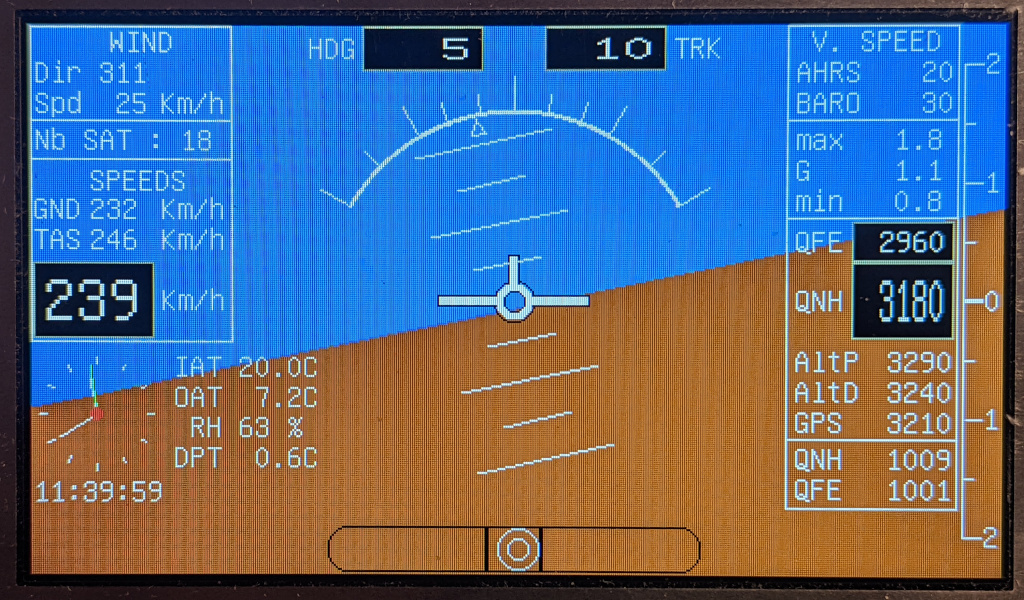
Compared to these two videos, the latest versions of the EFIS software (v2.5 and v3.0) bring some improvements to the presentation of data on the screen (fig. 7), as well as support for the different units of speed (Km/h, knots, MPH), pressure (hPa or In Hg) and temperature (°C or °F). Users can choose the units they want by navigating the menus using the rotary encoder. Their choices are saved in the EEPROM, as well as many other parameters (magnetic deviation, UTC time correction, display brightness, latest QNH and QFE, G max, and G min).
Flight data recorder analysis
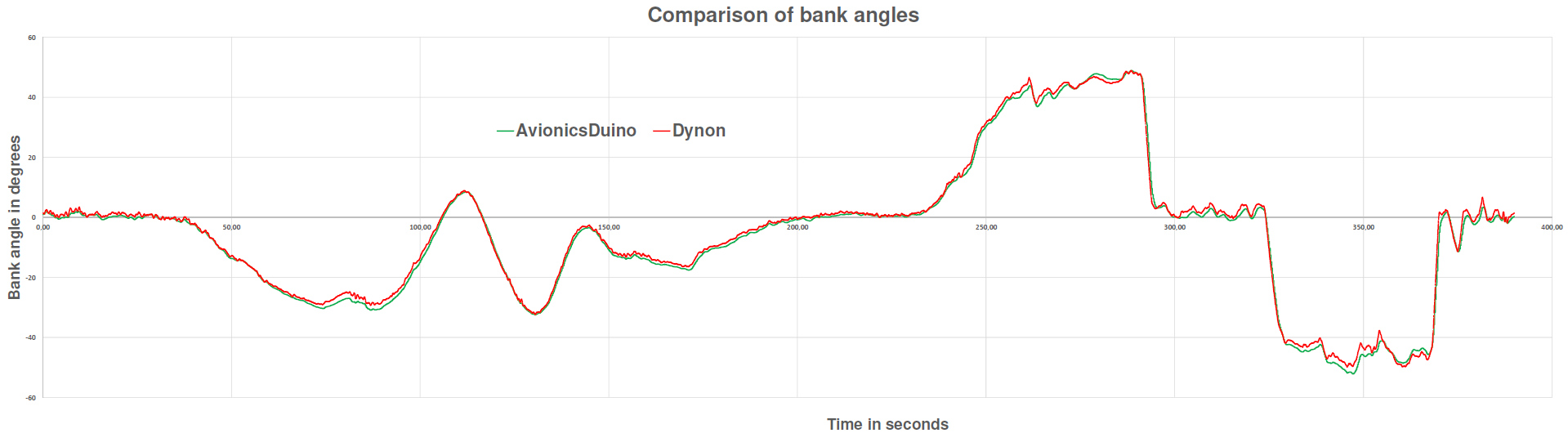
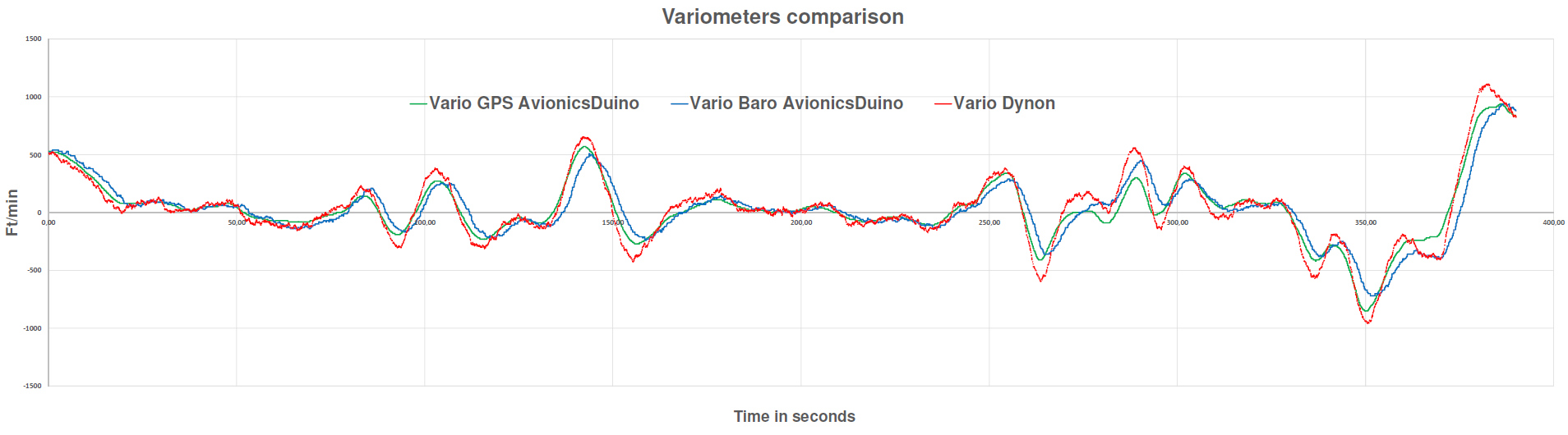
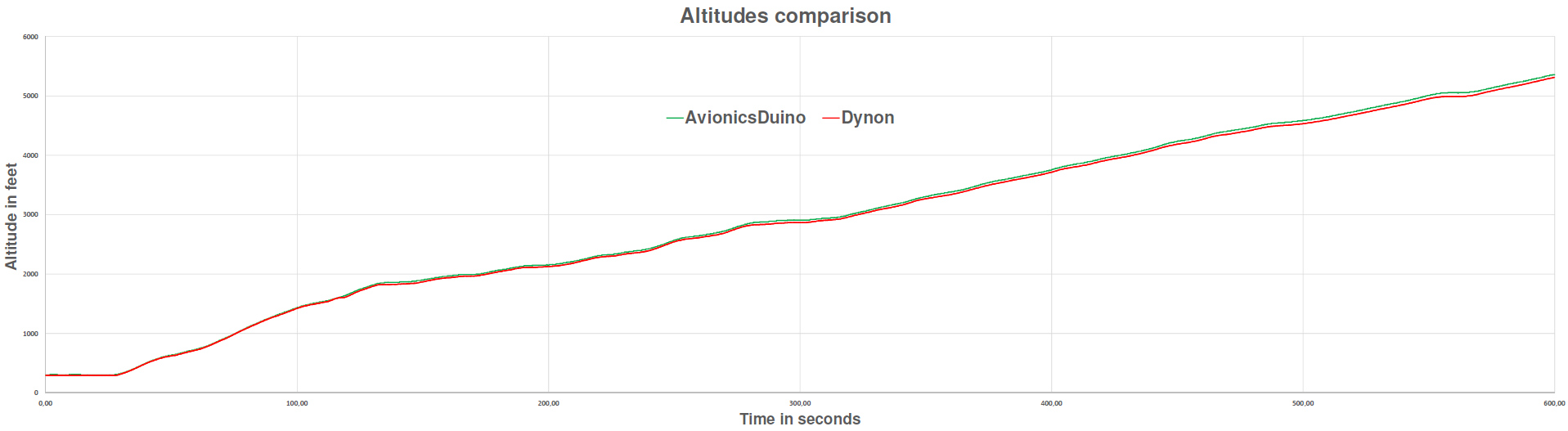
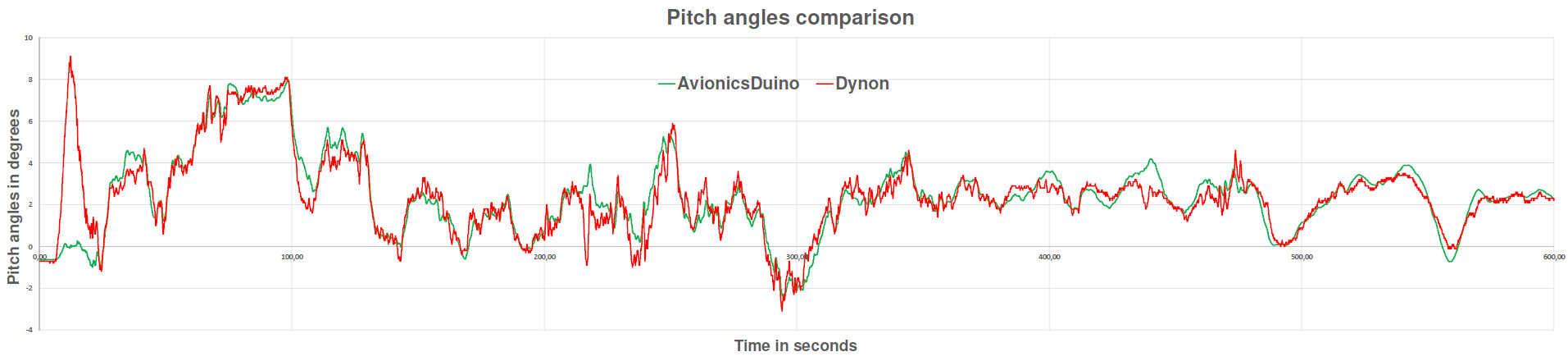
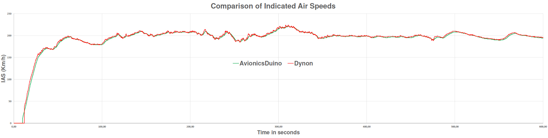
The graphs below were established with the data from the flight recordings; the x-axis is graduated in seconds. These graphs demonstrate the excellent correlation between the indications of the two EFIS. They validate our different hardware and software choices. You have to hover the mouse cursor over the curves to enlarge them.
Roll angle and variometer Comparisons
Altitude, pitch angle, and indicated airspeed comparisons
Hi Glen,
I haven’t started flight testing my new ESP32S3-based EMS-EFIS system yet. However, I’ve already installed the prototype’s power supply system and the connections to the static pressure and pitot probe circuits in the aircraft. All I need to do now is build a temporary enclosure. I have no particular concerns about the operation of this new system, which works perfectly on the test bench and uses the same sensors as the current Teensy-based system. It’s basically just a new data display system. Once the prototype has been validated in flight, I will group the EFIS pressure sensors and all the electronic circuits dedicated to the EMS sensors onto a single printed circuit board. The AHRS will be housed in a separate enclosure, as it is now, and the CAN bus configuration will remain unchanged.
Actually, I’ve been quite busy with another project over the past few weeks. I’ve been developing and starting flight testing a new leaning device system for my Rotax 912 engine. This device is a back-suction-type mixture control system that acts on the pressure inside the carburetor bowls via an electric vacuum pump. Two ESP32S3 boards also control the system. I have already been flight-testing a similar system for over a year, and it works perfectly, significantly reducing fuel consumption while cruising. However, it was much more rudimentary. The new system significantly improves reliability and safety. And it may allow for the introduction of a certain degree of automation in the future, for example, to maintain a constant air-fuel ratio; however, this is not the primary goal.
Benjamin
Any news on your new ESP32 board based EFIS-EMS project that is being finalized. I’m interested in building an EFIS system to test in my Rans S-21.
Thanks.
Hi Carlo,
Your EFIS-EMS-Teensy is an exciting contribution to the AvionicsDuino project.
Perhaps this superb achievement deserves more than a comment at the bottom of the AvionicsDuino website’s EFIS page.
As soon as you have tested it in flight, and if you agree, you could publish this EMS-EFIS here, on a new page. It should include all the explanations concerning the MGL Avionics RDAC decoder, the CARO0A04 CAN bus IO module, and how to wire the whole thing, along with nice diagrams, photos, and even in-flight videos.
I have a similar EFIS-EMS project that is being finalized. Now, all that remains is to test it in flight. The principle is different. It does not use Teensy boards but two ESP32 boards that communicate via ESP-NOW and a 7-inch screen. See the screenshot below. This new system will be published on the AvionicsDuino website as soon as flight tests are conclusive. In the next few months…
Benjamin
Moreover, in the new code area are included some methods to calculate temperatures using different senders (std VDO-120, PT1000 linear or interpolated).
I will try to write a better description of mi job as soon as possible if you you think it useful.
Greetings, Carlo
Hello Benjamin,
finally I’m able to share my homework!
I have just done some very little modification of you code (adding the Mag Deviation adjust on the General Menù). In the EIS menù the Flowmeter Kvalue can be adjusted, toghether with the Aivalable fuel in the tanks.
I have added also the procedure to manage the Adafruit MPRLS Ported Pressure Sensor
Breakout fot the MAP.
All the others have benn added to the main loop, at the end of your code, so that is very easy to understand where is new part of program.
Same thing has been done on the CAN bus handler, where I added the MGL Avionics RDAC decoder, the CARO0A04 CAN bus IO module (https://it.aliexpress.com/i/1005005372561647.html), that I used to read the Landing Gear and Flaps status, but also useful to drive some load if needed.
The RDAC is well documented (CAN protocol also) on the MGL website and uses the standard Rotax 912 senders.
The CAT sender (LM335) and 2nd Current sensor has been connected to the Fuel Inputs of RDAC, but of course everithing can be easily modified.
Each part of the graphical part has its own method that is clearly identified.
On the last screen area (bottom-right) the messages from the engine and flight parameter supervisor are printed, if Alarms, Warning or Advise to the pilot happen.
All the engine parameters can be found in the EMS.h file and they are related to Rotax 912ULS engine.
In the same header file there are the Aircraft airspeed limits and values use to manage the Landing Gear and Flaps position and to monitor the airspeed (alarms shown if close to Vs or Vne).
There is the possibility to disable the activated alarms “on the fly”, making checked = alarmflag. checked = 0, will disable this feature and reactivate all the alarms. This can be done, for example, with one menù function, to disable some alarm or to check the tank switch advise. I’m goig to include this function in the GEN Menù soon.
Always available for further info.
Best regards, Carlo
EFIS_EMS_Teensy_AvionicsDuino_CarloM_V1_0
Hi Skylar,
This is indeed very interesting. The definition of the photo does not allow us to identify all the components and sensors. I recognize an Arduino Nano ATmega328P board, the LIS3MDL magnetometer, and an RF spring antenna… You can share more details on this achievement in new comments if you wish.
I have completed the bench tests of a new sensor module that also communicates wirelessly (ESP-NOW) with an ESP32 display. I still have to proceed with the flight tests before being able to publish a new EMS-EFIS on a 7″ display on the AvionicsDuino website; more details will be provided in the next few months.
Benjamin
Hi Benjamin,
Regarding the most recent project posted (the Father & Son one), I’m the son who initiated the project. However, I’d like to highlight something important. When my father and I were working on our EFIS, we made a decision to create an external unit that houses both the pressure sensors and magnetometer. This external unit is wireless, making the EFIS adaptable for testing across different aircraft. I thought you may find that interesting.
Skylar,
Hi Nate and Skylar,
Awesome job! Please keep us posted when you flight test it. Thanks for sharing this great achievement!
Benjamin
Hi Benjamin,
Thanks so much for sharing. Your EFIS system has been a fun father and son project. We look forward to trying it.
Nate and Skylar
Hi Carlo,
Congratulations, and thanks for these photos.
To generate an image file readable by EFIS or EMS programs, you need to use the free image editing software GIMP to convert the image to XPM format, then a short Arduino program that will modify the XPM file to adapt it. For my use, I had written the whole procedure. The file that explains this procedure can be downloaded here. The .ino example program is downloadable here. It is in French but is very easy to translate using translation tools available on the web, such as Google Translate.
Best regards,
Benjamin
Hi Ben, I’m just giving the last brush hits to the SW and going to write a description of my add-ons!
Here some pictures of the work in progress and the main board upgrade with the manifold pressure sensor (connected to the third I2C bus). I could update the Kicad package if you want, but I will use thist hardware in my aircraft, as soon as I will have bonded wires and Adafruit board with silicon compound.
I want just ask you one thing, how do you create the photo.out file?
Best regards,
Carlo
Hi Carlo,
Congratulations on this awesome result!
Using the MGL RDAC XG is a bit out of the open-source DIY spirit and involves a significant additional cost, but it could help those who want to save time. From this perspective, your code could be very interesting. Thank you very much for your offer to share it here. You can attach it as a new comment in a zip archive.
I wish you a happy New Year 2025 and success in further development.
Benjamin
Hi Ben and happy new year!
I have just finished to draw the EFIS graphics to the 7″ Sunreadable display and this is the result.
I’m going to integrate an MGL RDAC XG as engine conditioning interface, but of course your EMS can be used just integrating the properly CAN bus message decoding.
Let me know if you like to have the code and wil send it.
Greetings,
Carlo
Hi Kirk,
Congratulations! Thank you for sharing this great success with a photo.
The menu algorithm is a bit complex. We could almost devote an entire page of the site to explaining it very precisely.
“OptionMenu” is a typedef structure, and “menu” is an array of this structure. This array acts as a database table containing all the items (options) of the menus/submenus.
Each “row” of the array is the equivalent of a record of this “table.” Each variable name of the structure is a field name of this table.
With the option numbers and index, this array allows the implementation of a simple, reliable, and efficient menu system while using minimal resources and memory. It is easy to maintain and upgrade. It is equivalent to a non-binary tree, without pointers, vectors, nodes, linked lists, or extra libraries.
Currently, a rotary encoder allows navigation in this menu tree. In the future version of the EFIS, which will be published on the AvionicsDuino website in 2025, a touch screen will facilitate this navigation and simplify the algorithm.
Here is an example of a menu tree with the labels and the option numbers.
Benjamin
Hello Benjamin, it is running. It’s amazing and wonderful experience you gave us.
I’m reading the menu code and but cannot understand it. Can you give me some instructions about the mechanism of “OptionMenu menu[] ” ?
Hi Kirk,
Many websites, such as this one, provide the formulas for calculating altitude based on static pressure.
For density altitude, it’s a bit more complex, for example see this didactic site.
If your question also concerns the definitions of QNH and QFE, it would be best to consult an airplane flying handbook or websites dealing with learning to fly, which is outside the scope of the AvionicsDuino website.
Regarding your question about magnetic heading, many libraries dealing with magnetometers give angular results in radians between -PI and +PI. Therefore, a conversion into degrees from 0 to 360 degrees is necessary. In addition, filtering the results during the passage from 360 to 0 and vice versa (or from +PI to -PI, and vice versa) requires some precautions.
Actually, an excellent way to better understand things is to manipulate these different sensors (pressure, magnetic, and many others) on the bench with your favorite MCU (Arduino, Teensy, ESP32, etc.) and a desktop computer.
Benjamin
Hello Benjamin,
I’m an amateur sport flight learner. I’m confused about the computing QNH and QFE, how to understand them. Where are the formulas from?
qnhAltitude = (1 - pow((((pressure + pressureCorrection * 10) / 100) / (QNH * 0.338646)), 0.190284)) * 145366.45 * altitudeCorrection; // 0.01 inHg = 0.338646 hPaqnhAltitude = int((qnhAltitude + 5) / 10.0) * 10;
qfeAltitude = (1 - pow((((pressure + pressureCorrection * 10) / 100) / (QFE * 0.338646)), 0.190284)) * 145366.45 * altitudeCorrection;
qfeAltitude = int((qfeAltitude + 5) / 10.0) * 10;
pressureAltitude = (1 - pow((((pressure + pressureCorrection * 10) / 100) / 1013.25), 0.190284)) * 145366.45 * altitudeCorrection;
I’m wondering about following processing of Mag heading? Is 360> magneticHeading>=0, or 180>=magneticHeading >-180, if it is in the former range, why does it happen that magneticHeading < 0,
if ((magneticHeading < 0) && (previousFilteredMagneticHeadingValue 0) && (previousFilteredMagneticHeadingValue > 270)){
previousFilteredMagneticHeadingValue = 0;
}
Hello again Benjamin,
HURRAH, I finally got everything programmed properly. Thanks to your write ups and my finally watching 3 different YouTube videos on proper naming conventions and how to install and sort Arduino libraries; I finally got everything straightened out and the programming went flawlessly.
My biggest issues were naming conventions. For instance, trying to get ILI6931 installed when in my library it was ILI_6931 with ILI_ 6931.h
It was a number of small errors like this that killed me. Once I took the time to compile, look at the error and then fix the library location or naming convention, it went quickly and smoothly. I’m looking forward to 3D printing some housings and getting everything installed. I ran everything on the breadboard and test bench today and it seems to be functioning well. Thank you for all the support you put into this.
Cheers,
Elton
Hello Elton,
It seems that you have placed some program files in the “libraries” folder of your sketchbook. This may be the reason for the errors.
Try again, but placing all the program files in the same folder, and of course removing the files that were mistakenly placed in the personal libraries folder.
The “EFIS_AvionicsDuino_V3.01” folder must contain the following files :
– AMS5915_simplified.cpp
– AMS5915_simplified.h
– EFIS_AvionicsDuino_V3.01.ino
– HorizArt.cpp
– HorizArt.h
– HorizArtParamGen.h
Benjamin
Hello Benjamin,
It’s been awhile. So I finally got back to playing with the Arduino sketch and managed to fix a few of my errors that were causing me headaches.
I believe that I only have 1 error outstanding, but I can’t seem to pinpoint it. I’ve attached my Arduino compile output for you. Have a look when convenient and let me know what you think.
Cheers,
Elton
EFIS sketch w errors
Thank you very much Benjamin, I’m very happy that you appreciate my system! You are right, I need a LiFePo3 battery to have no-break power and also an SSD because the SD failed a couple of times. It works fine, there are alarms in graphical form and also audio messages on the hearphones.
But I merry your opinion about the poor robustness of the operating system. Moreover, the raspberry generates a lot of EMI, that if not well shielded can blind the GPS receivers 🙁
I’m going to try to handle also the engine parts, starting from your EFIS. I think that only the RPM needs to be updated in few tens of milliseconds; the Oil pressure hundred ms and the others some seconds due the inertia of thermical mass and so on.
My congratulations for your AHRS, it seems to work very well.
I’m very happy that you published the cockpit of my Asso V; I will update here if I will get acceptable results!
Greetings,
Carlo
Hello Carlo,
Thank you for your kind comments.
Congratulations on your incredible avionics realization! The Raspberry really allows very high-quality graphics and perfectly fluid animations. As we can see in your photo, its power allows it to simultaneously manage an EFIS and an EMS on the same screen split into two parts.
However, in return, it is necessary to add a power supply system using a rechargeable battery that can safely shut down the operating system in case of an unexpected loss of power. An Uninterruptible Power Supply unit complicates the system and increases the risk of failures. This is why we abandoned the idea of the single-board computer despite some visually appealing preliminary tests using Processing and Python.
Therefore, we chose to use microcontrollers without an OS, which implies being a little less demanding of the quality and realism of the graphics, particularly that of the artificial horizon.
With this reservation, I am convinced that the enormous computing power of a Teensy 4.x board could easily manage the display of an EMS and an EFIS on an 800×480 TFT, with a graphics controller like the RA8875, with its two layers which allow, despite the absence of vertical synchronization, to eliminate all flickering. But I have not tried…
Nothing prevents using several microcontrollers working together to manage the many sensors (as you do), as long as only one manages the screen.
I imagine a screen in two parts, like in your photo, rather than an EFIS page and another EMS page. It is better to have all the information on a unique page at the same time.
We are currently testing a completely different display system based on an ESP32-S3 managing a 16-bit parallel bus and an optimized library using sprites and touch control, dramatically improving the visual aspect and fluidity.
We will provide more details later (2025) on this new system, which will use the same sensors as our current system and will, therefore, be interchangeable with it without changing anything else. I’m not sure an ESP32-S3 can manage both EMS and EFIS and complex graphics on the same 800×480 TFT display with an acceptable frame-per-second rate. Perhaps it’ll be better to use two superposed screens in landscape mode.
Benjamin
Hello Benjamin,
my compliments for your job, it’s a very good job. I have a similar project on my ULM but based on a ATMEGA128 (for signal conditioning) and a Raspberry for the main display. I have just realised your AHRS and EFIS boards using my present LCD 7″ 800×480 1000 NITS because I don’t like to have an OS inside an avionics instrument (like mine)! Have you ever thought about to join the EFIS and EMS on the same main display?
Could be one page for flight and a second for engine monitoring…
Can you see any obstacle to do this?
Best regards,
Carlo
Hello Sergio,
I don’t know Spanish, but thanks to Google Translate, I believe your question is about ordering PCB from PCBWay.
The best solution would be to start by visiting the PCBWay website and reading their instructions carefully.
All the necessary Gerber files for each PCB are available for download on the avionicsduino website.
I hope this helps.
Benjamin
Buenos dias benjamín,
Como puedo pedir exactamente esta placa a pcbway? Para empezar a construir
Gracias
Hi Giuliano,
PCBWay is mainly a PCB manufacturer, not a seller of electronic components.
You should probably just order the PCBs from them and buy the components individually. The BOM has a vendor column with a link for each component to the supplier. You then have to solder the components onto the PCB yourself. If you don’t have the experience, you can probably get help from a friend. Furthermore, there are plenty of online tutorials to help you soldering SMD.
The AvionicsDuino website is not commercial and cannot sell you a ready-made PCB.
Benjamin
Good morning,
i’m trying to assemble this beautifull Avionicsduino. Unfortunatly i’m pretty to zero with eletronics skills.
Anyway i sent an email to pcbway in order to buy all the component and i have an issue of out of stock for some peaces.
Someone could help me? I no want buy wrong incompatible material.
Thank you
Giuliano
BOM di PCBWay
BOM di AvionicsDuino v2.1
Hello Elton,
Your compilation issue is a bit difficult to analyze and understand.
At the end of your verbose output log file (the list of all libraries used), I noticed that some libraries are not installed in the usual place. This concerns the following three lines:
Using library Adafruit-GFX-Library-master at version 1.11.10 in folder: C:\Program Files (x86)\Arduino\libraries\Adafruit-GFX-Library-master
Using library Adafruit_BusIO-master at version 1.16.1 in folder: C:\Program Files (x86)\Arduino\libraries\Adafruit_BusIO-master
Using library TeensyTimerTool-master at version 1.4.1 in folder: C:\Program Files (x86)\Arduino\libraries\TeensyTimerTool-master
These three personal libraries are not part of the standard TeensyDuino installation. Generally speaking, modifying, deleting, or adding files in the IDE or TeensyDuino installation folders is not recommended. I suggest you move these three libraries to the “libraries” folder of your sketchbook, i.e., in the following folder :
C:\Users\elton\Documents\Arduino\libraries
These libraries should no longer appear in C:\Program Files (x86)\Arduino\libraries\
It is not impossible that this will at least partially solve the compilation problem. See error #2 below: the conflicting declaration is possibly related to the wrong folder of the Adafruit-GFX library.
Furthermore, searching for the keyword “error:” in your verbose output log file, we find two occurrences:
1- C:\Users\elton\Documents\Arduino\EFIS_AvionicsDuino_v3.01\EFIS_AvionicsDuino_V3.01.ino:967:21: error: ‘CAN_message_t’ does not name a type
2- C:\Program Files (x86)\Arduino\hardware\teensy\avr\libraries\ILI9341_t3/ILI9341_t3.h:170:3: error: conflicting declaration ‘typedef struct ILI9341_t3_font_t ILI9341_t3_font_t’
The first occurrence is mysterious, and it could make you think that the FlexCAN_T4 library was not included, which is not the case. At the moment, I have no explanation.
The second occurrence is possibly related to the wrong folder of the GFX library.
Could you start by fixing the problem of the wrong folder for the three above-mentioned personal libraries?
Cheers,
Benjamin
Hello Benjamin,
So I finally got back to my work. All boards are done and systems built. All I need to finish is programming. I’ve attached my compiling output (including errors). Thank you for your help, it is much appreciated.
Cheers,
Elton
Arduino 1.8.19 (Windows 10), TD 1.5
Hi TingYun,
Congratulations. I suspected this kind of issue while watching your video.
However, your changes will be lost the next time you update Teensyduino.
You could have instead modified the EFIS sketch similarly to suit your encoder.
Benjamin
Thank you for your reply, sir
I have resolved the issue with the rotary encoder
Modifying QuadEncoder files
As shown in the following figure
Hello TingYun,
I was not able to find the datasheet of the MK012244 encoder, so I am not certain that I can really help you a great deal. .
Here is the datasheet of the Grayhill optical encoder we use. Please read carefully the “WAVEFORM AND TRUTH TABLE” subsection. This encoder has an operating voltage of 5.00 ± 0.25 V, but it works perfectly well with 3.3V. It is immediately available from Digikey, Mouser, and many other electronic wholesalers.
If you don’t want to use the Grayhill encoder, you may need to experiment with any other available encoder with one or the other examples of the QuadEncoder library. Some encoders may need external pullup resistors, and you should be sure it works with 3.3V. But if the waveform and the truth table differ from the Grayhill ones, you may need to modify the software accordingly by yourself.
Maybe using the Grayhill encoder is the most simple and fast solution…
Benjamin
Hello sir.
I couldn’t find the Grayhill encoder when making the circuit
I am using the regular rotation code MK012244
After welding, there are problems.
Rotate the encoder forward one grid, and the page will display 4 grid jumps.
It’s too sensitive.
How does this need to be improved.
video
Hi Elton,
It’s difficult to understand exactly what happens and why you can’t compile the EFIS sketch.
Sure, you don’t need to have any board connected to your computer to compile. An SD card is not necessary. You only need to select the proper board (Teensy 4.1) in the Tools menu.
Please tick the compilation and upload boxes in the “Show verbose output” section of the Preferences Menu.
Then press CTRL+R (option Verify/Compile in the Sketch menu).
At the end of the compilation, please copy-paste all the verbose output to a text file, then make a new comment and attach this file to your comment.
I hope I will then be able to understand what’s going wrong.
Benjamin
Hi Benjamin,
–
Well, I am almost at my wit’s end (not that I have a lot of wit to spare), but I’ve re-imaged my computer, loaded it without any external influence (bloody MS One Drive), and have made sure all of my versions for the library are correct. No double library anywhere, no changes to Arduino program x86 library and I’m still not able to compile. I know it’s something I’m missing, but at this point in time I’m almost thinking of sending you my Teensy 4.0’s and 4.1 and a small fee to image them for me.
It sounds like a stupid question, but do I need the 4.1 board and SD card with the MOUNTBLANC 2 hooked in and running to be able to compile?
Hello Elton,
I have exactly the same configuration : Arduino: 1.8.19 (Windows 10), TD: 1.59, Board: “Teensy 4.1, Serial, 600 MHz, Faster, US English”. With this configuration, no compilation issue for EFIS_AvionicsDuino_V3.01.ino.
The files EFIS_AvionicsDuino_V3.01.ino, AMS5915_simplified.cpp, AMS5915_simplified.h, HorizArt.cpp, HorizArt.h, and HorizArtParamGen.h are in this folder :
C:\Users\BF\Documents\Arduino\EFIS_AvionicsDuino_V3.01
Here are the versions of the libraries used and their folders:
Using library EEPROM at version 2.0 in folder:
C:\Program Files (x86)\Arduino\hardware\teensy\avr\libraries\EEPROM
Using library SPI at version 1.0 in folder:
C:\Program Files (x86)\Arduino\hardware\teensy\avr\libraries\SPI
Using library RA8875 at version 0.7.11 in folder:
C:\Program Files (x86)\Arduino\hardware\teensy\avr\libraries\RA8875
Using library OneWire at version 2.3.8 in folder:
C:\Program Files (x86)\Arduino\hardware\teensy\avr\libraries\OneWire
Using library Time at version 1.6.1 in folder:
C:\Program Files (x86)\Arduino\hardware\teensy\avr\libraries\Time
Using library SD at version 2.0.0 in folder:
C:\Program Files (x86)\Arduino\hardware\teensy\avr\libraries\SD
Using library SdFat at version 2.1.2 in folder:
C:\Program Files (x86)\Arduino\hardware\teensy\avr\libraries\SdFat
Using library QuadEncoder at version 1.0.0 in folder:
C:\Program Files (x86)\Arduino\hardware\teensy\avr\libraries\QuadEncoder
Using library Adafruit-GFX-Library-master at version 1.11.9 in folder:
C:\Users\BF\Documents\Arduino\libraries\Adafruit-GFX-Library-master
Using library Adafruit_BusIO-master at version 1.14.5 in folder:
C:\Users\BF\Documents\Arduino\libraries\Adafruit_BusIO-master
Using library Wire at version 1.0 in folder:
C:\Program Files (x86)\Arduino\hardware\teensy\avr\libraries\Wire
Using library ILI9341_fonts-master at version 1.0 in folder:
C:\Users\BF\Documents\Arduino\libraries\ILI9341_fonts-master
Using library TeensyTimerTool at version 1.4.1 in folder:
C:\Users\BF\Documents\Arduino\libraries\TeensyTimerTool
Using library FlexCAN_T4 in folder:
C:\Program Files (x86)\Arduino\hardware\teensy\avr\libraries\FlexCAN_T4 (legacy)
Your file organization seems to me like a mess, and it’s probably the reason for your compilation errors.
For exemple: E:\AHRS Data\EFIS-AvionicsDuino-main (1)\EFIS-AvionicsDuino-main\src\V3.01
\EFIS_AvionicsDuino_V3.01\EFIS_AvionicsDuino_V3.01.ino
Wow! What a long and exotic path!
More seriously, many readers experienced similar issues, so I decided to write a dedicated page about the Arduino IDE in the hope of helping to prevent these compilation issues. I’m sorry, but I haven’t yet taken the time to translate it into English. But with the help of your browser’s translation option, you should probably be able to read this French page without too much difficulty.
I hope this information helps. Don’t add or delete anything in the IDE or TeensyDuino installation folders. All your personnal libraries must be installed in the “libraries” folder of the “Arduino” folder (your Sketchbook). Don’t hesitate to uninstall and reinstall everything properly!
Benjamin
Hello again Benjamin,
Sorry to bother you with what is probably a trivial item, but I keep getting the error below. I’ve gone into my libraries and made sure that both the new version of ILI9341 and RA8875 are both in the library. This seems to be the only error left. Any help is appreciated. Cheers, Elton
Arduino: 1.8.19 (Windows 10), TD: 1.59, Board: “Teensy 4.1, Serial, 600 MHz, Faster, US English”
In file included from C:\Program Files (x86)\Arduino\hardware\teensy\avr\libraries\ILI9341_t3/font_Arial.h:4,
from E:\AHRS Data\EFIS-AvionicsDuino-main (1)\EFIS-AvionicsDuino-main\src\V3.01\EFIS_AvionicsDuino_V3.01\EFIS_AvionicsDuino_V3.01.ino:109:
C:\Program Files (x86)\Arduino\hardware\teensy\avr\libraries\ILI9341_t3/ILI9341_t3.h:170:3: error: conflicting declaration ‘typedef struct ILI9341_t3_font_t ILI9341_t3_font_t’
170 | } ILI9341_t3_font_t;
| ^~~~~~~~~~~~~~~~~
In file included from C:\Program Files (x86)\Arduino\hardware\teensy\avr\libraries\RA8875\src/RA8875.h:214,
from E:\AHRS Data\EFIS-AvionicsDuino-main (1)\EFIS-AvionicsDuino-main\src\V3.01\EFIS_AvionicsDuino_V3.01\EFIS_AvionicsDuino_V3.01.ino:103:
C:\Program Files (x86)\Arduino\hardware\teensy\avr\libraries\RA8875\src/ILI9341_fonts.h:25:3: note: previous declaration as ‘typedef struct ILI9341_t3_font_t ILI9341_t3_font_t’
25 | } ILI9341_t3_font_t;
Hi Michael,
Thanks you for your interest in the AvionicsDuino website. You can count on our assistance via these comments if you decide to build either of the systems described here.
You can find a link to a Github repository with all necessary software on each of the following pages : EFIS, AHRS, Digital compas, EMS, and Micro-EMS.
For each software, the references for all necessary libraries are clearly indicated.
In USA, I think you can purchase AMS5915 pressure sensors from Servoflo Corporation. All other components from electronics wholesalers such as Digikey, Mouser…
Benjamin
I am interested in trying to build this. But before I start, I wanted some sense that I could follow your lead to complete this before ordering all of the sensors. I looked for the arduino code under “Software” but didn’t find any links to it. Did I miss something?
I was also interested in how you got the pressure differential sensor to work under I2C. Is there a driver / library for it somewhere? I found other analog pressure differential sensors, but I was hoping that this one would be more accurate.
Hi Roberto,
I should write a page in the software section of the site about these speed calculations… And also for the calculation of altitudes, and more particularly, the density altitude. Just a matter of time!
All the best,
Benjamin
Benjamin, thank you very much for your exaustive and accurate explanation!!!
Now is everything much clear!
cheers
R
Hi Roberto,
I moved your comment from the AHRS page to the concerned EFIS page.
Thank you for this comment and giving me the opportunity to redo my calculations, I found an error!
Lest’s see how the constants used were obtained.
It is assumed that the Pitot tube is ideally installed, and therefore the CAS (Calibrated Air Speed) is equal to the IAS (Indicated Air Speed). We also postulate that at a speed below 300 km/h, air behaves like a non-compressible fluid, therefore the EAS (Equivalent Air Speed) is equal to the CAS.
Indicated airspeed (IAS) can be approximated in m/s by the following equation obtained from Bernoulli’s equation:
where:
– Pt is the total pressure in pascals,
– Ps is the static pressure in pascals,
– ρ0 is the air density at sea level in standard atmosphère in kg/m3.
Given that Pt-Ps = differential pressure (Pd), and ρ0 = 1.225 Kg/m3, equation 1 become:
We want IAS in Km/h so :
True airspeed (TAS) can be obtained in m/s by the following equation:
where ρ is the air density at the aircraft’s flight altitude
Given that the density of dry air (in Kg/m3) can be calculated using the following formula, obtained from the ideal gas law:
where:
– Ps is the static pressure in pascals at the aircraft’s flight altitude,
– M is the molar mass of dry air, approximately 0.0289652 in kg/mol,
– T is the absolute temperature in degrees Kelvin (= degrees Celsius + 273.15),
– R is the universal gas constant, or ideal gas constant, approximately 8.314462618 in J °K−1 mol−1,
combining equation 2 and equation 3, we obtain:
We want TAS in Km/h so:
So the constant currently used in the EFIS software for the TAS calculation (i.e. 84.9528) is wrong! It should be 86.2574! I can’t remember how and why I obtained 84.9528…
I have modified the software accordingly in the GitHub repository.
Benjamin
Hi Benjamin,
please forgive my ignorance but i can’t get how works your formulas for IAS and TAS, in particular what is 21.159144 in IAS and 84.9528 for TAS.
Thank you very much
R
Hello Brent,
Thank you for your kind comments.
Apart from the AMS5915 pressure sensors, which must be ordered directly from AMSYS in Germany (for Europe), almost all other components are, in principle, available from the usual wholesalers (Digikey and Mouser, for example). Some elements are also available on eBay or Amazon. Of course, there can sometimes be stock shortages, which we hope are as short as possible.
In case you couldn’t find a particular item, don’t hesitate to post a new comment.
Benjamin
Hi, is there anywhere that has all the components at one online store? It’s rather difficult to find all these items in Australia. Fantastic work….. you’ve basically pushed through every single stumbling block i encountered and couldnt work out!! Thanks.
Hi Tim,
Thank you for your comment. You are right. Things are not readily evident because two versions of the EFIS coexist on the same page. I must thoroughly update the English and French pages on EFIS with only the latest version. The history of things is not so attractive. Old photos or videos of the first prototypes are useless.
To answer your question more precisely, only one GNSS is needed. It is located in the AHRS module. The GPS connector on the EFIS PCB and the antenna connector on the EFIS-EMS aluminum case are useless. They are only there for historical reasons. The AHRS and EFIS programs are up to date for single GNSS operation.
Benjamin
I read on the French site that you were possibly going to modify the programing to use only one GPS module. Has that update been performed or does this project still require 2 GPS modules?
Thank you.
Hi Alfredo,
There are currently no menu options to convert speed and pressure units to mph and inHg. Implementing such options would be relatively easy, so I’ll put that on my to-do list. However, this list is already long…
That said, if you want to do it yourself now, instead of modifying menu options, which can be tricky, a faster and easier alternative could be to modify a few lines in the code if you never use km/h, knots, and hectopascals. Manifold pressure is already in inHg in the EMS.
Benjamin
Very interested in your project. What would be needed to convert units to mph and inHg? TIA
If I translate Portuguese correctly, your question is: “Where do you recommend buying the kit?”
There is no ready-to-assemble kit for sale.
For each circuit described on this site, you can download Kicad or Gerber files which will allow you to order the printed circuit board from a PCB manufacturer (Aisler in Europe, OSH Park in the United States, JLCPCB and PCBWAY in China, for example)
You can also download the component bill of materials, indicating each component’s supplier.
It is up to you to solder the components on the PCB. By the way, some PCB manufacturers can assemble all the components for you on the printed circuit boards.
The AvionicsDuino website does not give instructions for integrating circuits on an instrument panel because electrical circuits and instrument panels are so different in the world of homebuilt and ultralight aircraft.
Some will aim to facilitate practical realizations among the coming soon pages on this site. For example, soldering surface mount components, preventing electromagnetic interference, CAN bus…etc.
Stay tuned for updates.
Benjamin
onde indica comprar o kit?
Hi Massimo,
Thanks for your kind comment.
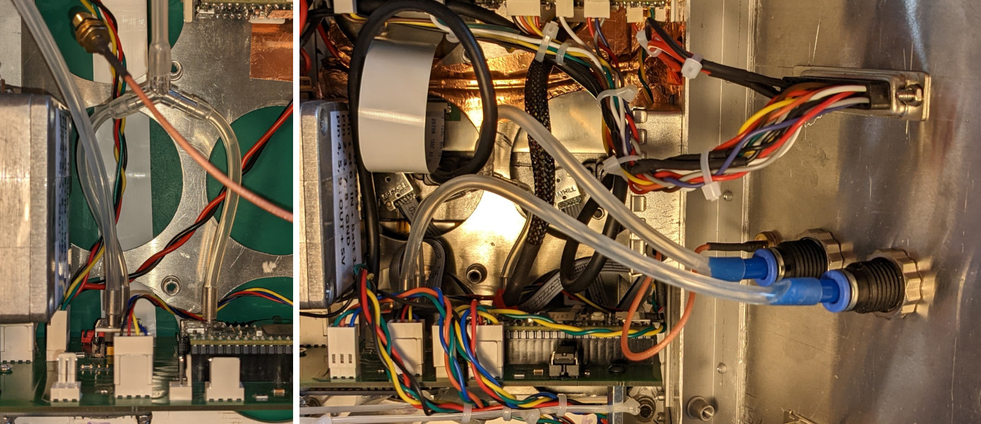
Please see the picture below showing the connections from the pressure sensors to the EFIS static and Pitot port input :
Pneumatic bulkhead fitting D6
Thick wall silicone tubing : many sizes available
Polyurethane pneumatic tubing
Plastic T connectors
Benjamin
Hi, how did you connect togheter the AMS 5915 0050D static port and the 5915 1500A port to the EFIS static port input? Btw, great project!!!!
Hi Shane,
For EMI purpose, we prefer aluminium cases, so no 3D printed stuff.
A new, more advanced EFIS prototype will very soon be tested in flight, as well as a new EMS, far more complete than the micro-EMS already described. This EMS is based on an extensive characterization study of all temperature and pressure sensors of the Rotax engine. So several new articles very soon on AvionicsDuino!
3D printed stuff?
let me know if you ever need any 3D printed parts or resources!
i need and EFIS! anything i can do to help!
Shane