(EMS: Last updated by Benjamin on November 09, 2023)
Monitoring aircraft engines has long relied on analog gauges: RPM, oil pressure, intake manifold pressure, various temperatures, etc. Nowadays, all these instruments are often replaced by an EMS (Engine Monitoring System), where information from many sensors is centralized and displayed on a single screen.
This page will describe the main unit of the AvionicsDuino EMS. The reader is invited to refer to this site’s “Hardware” section. It contains the description of most of the sensors of the Rotax 91x engines. These engines are ubiquitous in amateur-built, experimental, and ultra-light aircraft. Sensors used on other engines are sometimes identical or very often based on similar principles. Many sensors studied in the “Hardware” section are not specific to Rotax engines (thermocouples, shunts, O2 probes, flow sensors, etc.)
AvionicsDuino EMS general presentation
The following parameters are monitored directly by the main unit of the EMS:
- Temperatures of cylinder heads 2 and 3
- Oil temperature and pressure
- Intake Manifold pressure
- Endurance bus voltages
- Battery charge/discharge current
- Current drawn by the main bus
- AFR (Air Fuel Ratio) in connection with the O2 probe
- Exhaust gas temperatures of cylinders 3 and 4
Other essential parameters are monitored via the Teensy micro-EMS. This micro-EMS is to be considered an integral part of the EMS system. These parameters are transmitted over the CAN Bus and displayed on the screen of the EMS main unit. These parameters are:
- RPM
- Fuel flow
- Fuel level in the tank (calculated and measured)
- Battery voltage
EMS general architecture
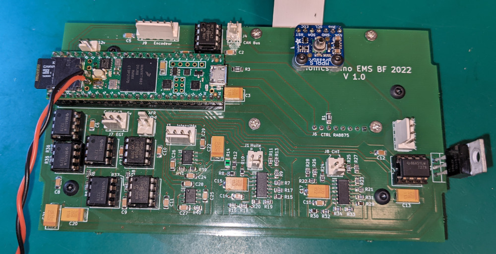
The Micro-EMS occupies the upper part of this diagram. The EMS main unit is at the lower part. The heart of the main unit is a Teensy 4.1 board (fig. 1). Its display is a 5″ color TFT (Riverdi TFT LCD 800x480px 1000cd/m2 IPS 5.0″ RVT50HQTFWN00). The two units communicate via the CAN bus.
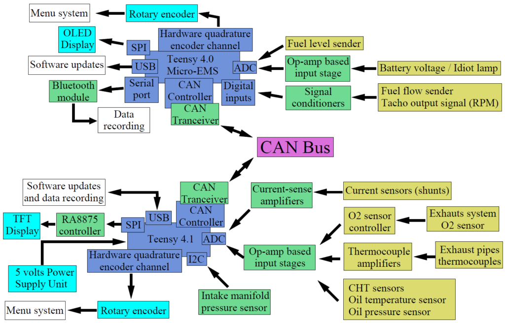
Apart from the digital manifold pressure sensor, which is connected to one of the Teensy I2C buses, and the sensors supported by the micro-EMS, all other sensors have an analog output and provide a signal that is a continuous voltage between 0 and 3.3 volts for some, between 0 and 5 volts for others.
These voltages must be digitized by one of the analog-to-digital converters (ADC) of the Teensy 4.1 board. Before that, they are processed by an appropriate input stage, either to adapt the impedances, to bring the voltages from the 0-5v range back to the 0-3.3v range, to amplify low voltages to drive an ADC to full-scale value or to apply an offset if necessary, and sometimes for several of these reasons.
These input stages use operational amplifier technology and are described in detail in the various pages devoted to sensors in the “Hardware” section. The resistors that control the gains and offsets of these op-amps all have tolerances of 0.1%, allowing for high precision results. Our experimental measurements have shown precision to the nearest degree for temperatures in the range of 50 to 150°C, thanks also to the rigorous modeling of the sensors (see the page on temperature sensors in the “Hardware” section).
EMS V1: Download Kicad 6 files
EMS V1: Download Gerber and drill files
EMS AvionicsDuino: Download source code on GitHub
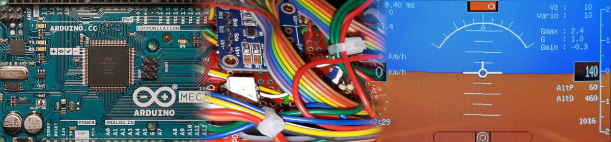
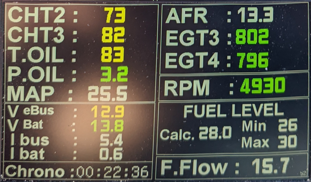
The video below was made during one of the first test flights with the EFIS-EMS AvionicsDuino on September 3, 2022. The EMS software was still in the very first test version. The download version above brings many improvements: implementation of the intake manifold pressure, a menu system, a stopwatch, a function allowing the connection to the flight data recorder, and, of course, correcting some bugs (fig. 7).
The highly stripped-down interface is exclusively alphanumeric. Without desire for aesthetics, but highly functional and readable. All the essential elements are there. If preferred, developing a beautiful GUI later would be simple.
The rotary knob and the micro-USB socket on the left are those of the EFIS. The same items on the right are for EMS. The USB sockets allow connection to the flight data recorder and the uploading of software updates to the two Teensy 4.1 boards.
Hi Robert,
The fontesLCD.h file is in the same GitHub folder as the main program file (EMS_AvionicsDuino_01_7.ino). See here.
On your computer, you need to place the fontesLCD.h file in the same folder as the .ino file. The same applies to the Rotax912.OUT file.
Benjamin
Hi, I have the problem as a amateur to compile the sketch, as I can’t find the necessary ‘fontesLCD’ anywhere. The ILI9341_fonts are installed, but they don’t include any LCD fonts.
Hi Tim,
Thank you for your kind comment. I moved it from the home page to the EMS page.
You can add as many CHT and EGT sensors as you want, but you need to make substantial changes to the circuit and the PCB or use the current circuit with external rotary switches to select between the source sensors.
The abovementioned changes in the circuit can be adding more input stages (but the number of available analog pins of the Teensy board is limited) or, better, adding a multichannel analog multiplexer (74HC4067, for example).
Benjamin
Great work. Very impressive. You have quite a skill.
Is it possible to add additional CHT and EGT sensors for use in a 6 cylinder engine? Perhaps to aid in operation at LOP.