(Teensy Micro-EMS: last updated by Benjamin on May 19, 2024)
A Teensy 4.0 board is the heart of this completely redesigned version of the Micro-EMS. This new system provides the same functions as the Arduino Micro-EMS. Namely RPM measurement, fuel level and flow management, and battery voltage monitoring, with an “Idiot Lamp.” The Arduino Micro-EMS was initially designed as a stand-alone instrument, then evolved with the addition of a connection to the aircraft CAN network. This new version was designed from the outset with an integrated modular avionics perspective.
Presentation of the Teensy Micro-EMS
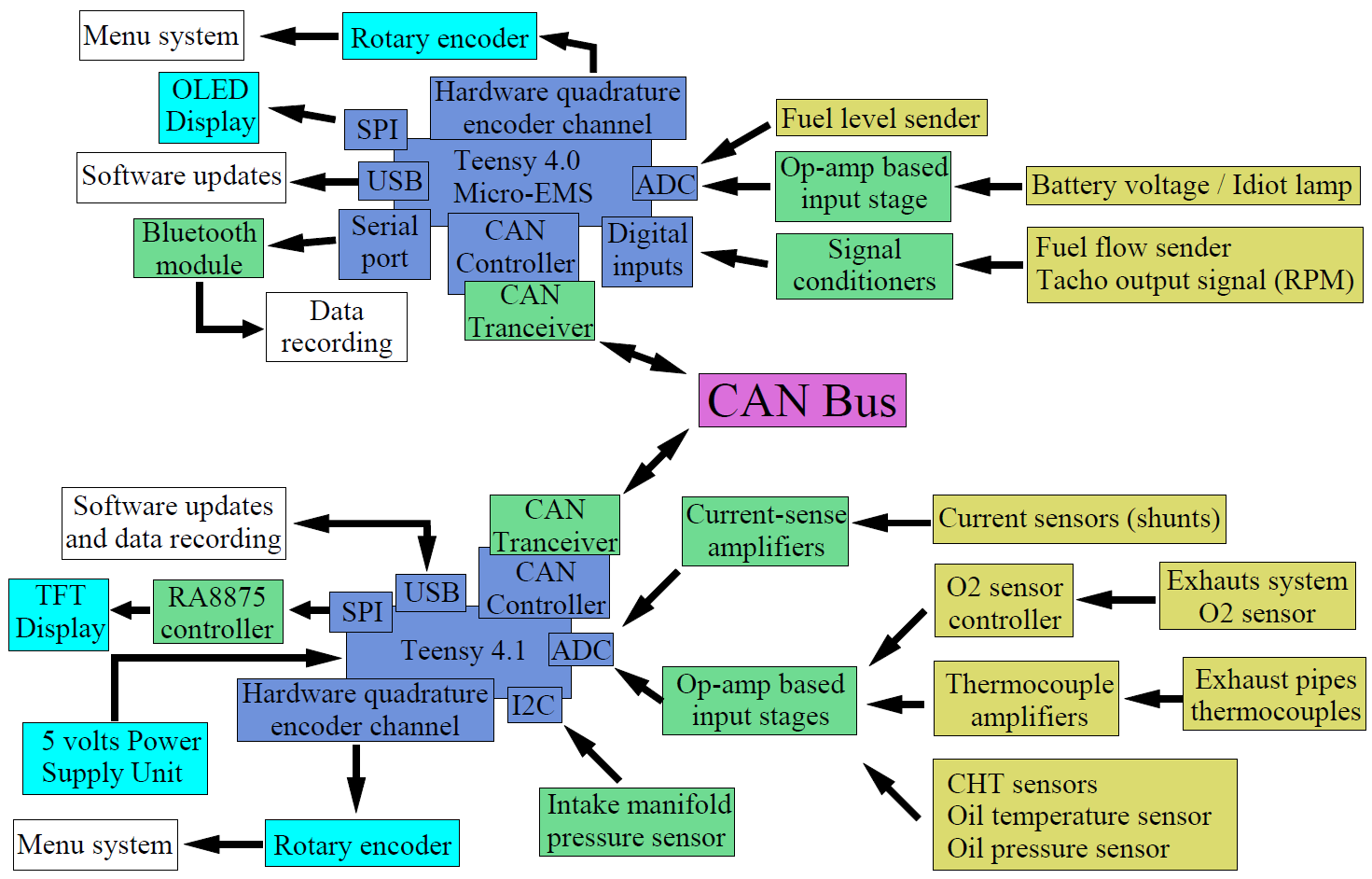
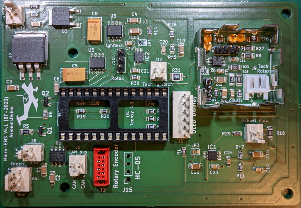
Therefore, the Teensy Micro-EMS module should be considered an integral part of the Engine Monitoring System, or EMS, whose general architecture is shown in Figure 1. The Micro-EMS occupies the upper part of this diagram. The EMS main unit is at the lower part. There have been several successive versions of the printed circuit board (PCB), and the test flights have made it possible to gradually improve and correct the initial defects, particularly of the rev counter function. The PCB shown on this page is version 4.1. The current software version is 4.04.
Description of the system
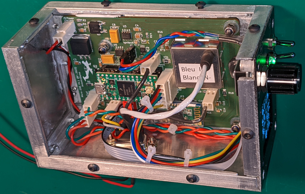
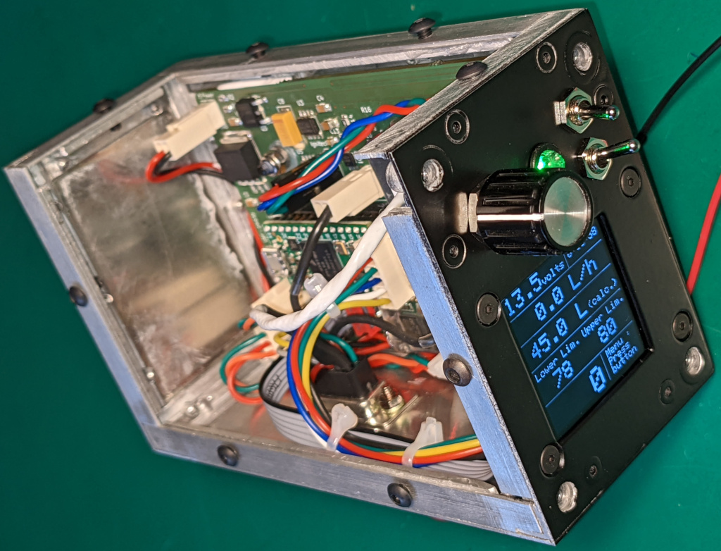
This new Micro-EMS is mounted in the same MCR Sportster, replacing the previous one (see figures 2 to 7 below). The first Teensy version (PCB v 3.1) was installed in April 2023. Subsequently, the system was extensively flight-tested, which led to its modification and improvement. The current version (PCB v 4.1) is mature and has been in flight since October 2023.
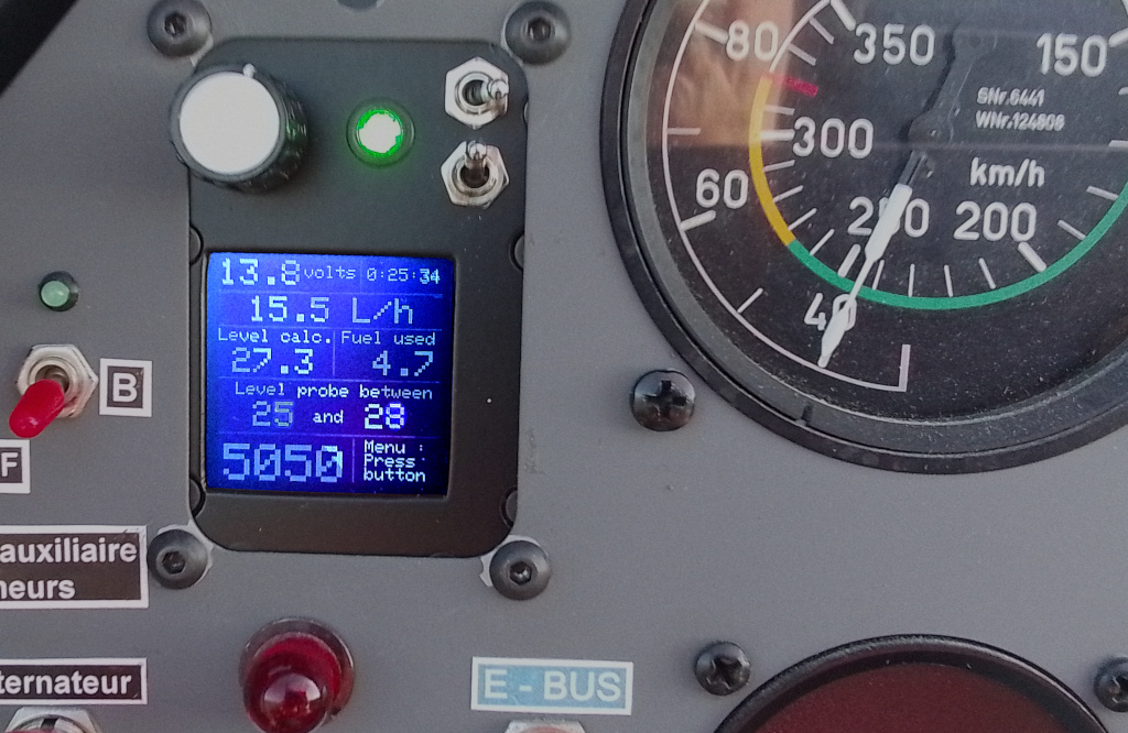
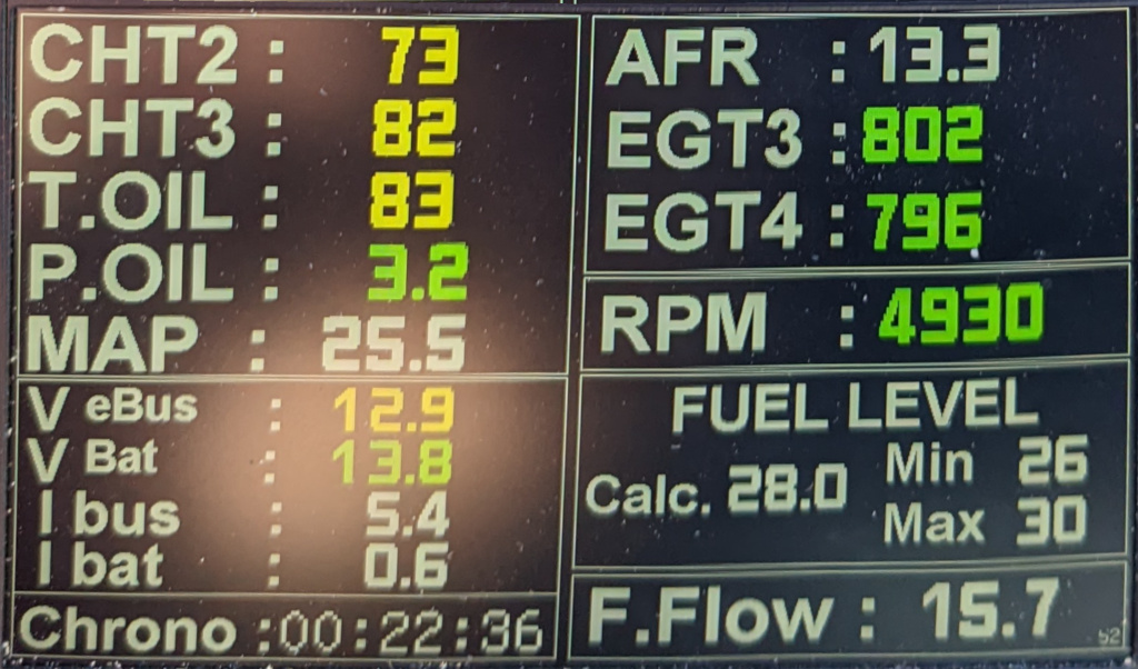
It is more compact. A small 128×128 monochrome OLED display has replaced previous versions’ 2.2-inch Adafruit TFT display. This display is actually an accessory display. The 5″ display of the EMS is the prominent display of the system. A rotary encoder has been added to allow navigation in a straightforward menu system. An HC-05 Bluetooth module allows in-flight recordings on a smartphone or tablet with Serial Bluetooth Terminal. This last function is incidental. Based on an ESP32 board connected to the CAN bus, the global flight data recorder is much more efficient and reliable.
Photo gallery
Download links
Download software on GitHub. (The Micro_EMS_V4_06.ino file, or later, must be used with version 4.1 of the PCB. The Micro-EMS_V3_2.ino file is left on the GitHub repository to help the reader who would like to take inspiration from it to implement a graphics TFT display instead of the small 128 x 128 OLED)
Micro-EMS connections to aircraft circuits
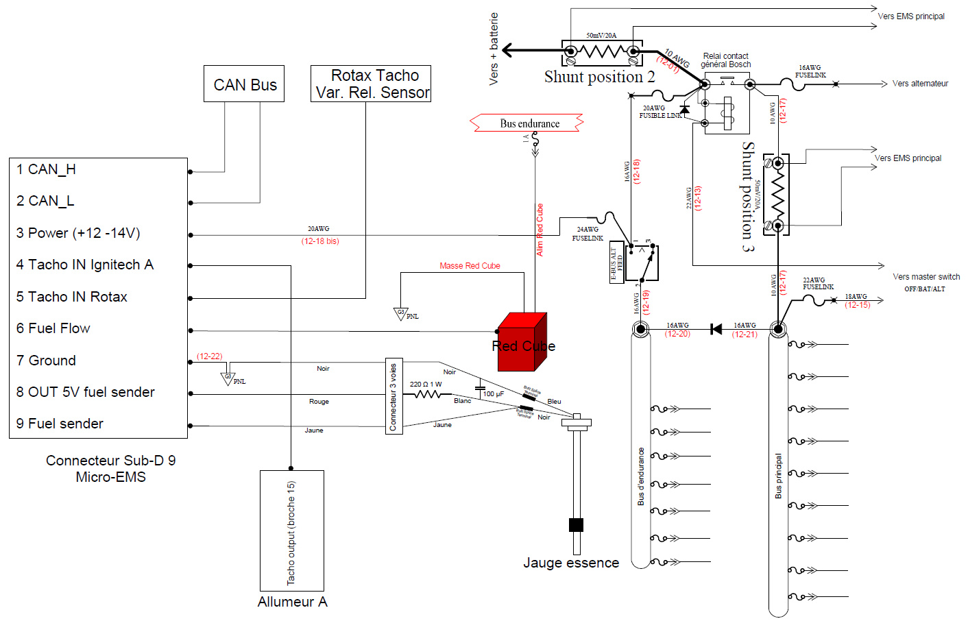
The connections of the Micro-EMS to the aircraft circuits are shown in Figure 8 (hover the mouse pointer over the image to enlarge it). These connections use a 9-pin D-SUB connector.
12-14 volts power supply
The power supply (D-Sub pin 3) comes directly from the aircraft battery through 2 fuse-links and the shunt in position 2. A switch on the instrument panel, not shown in Figure 8, allows turning the Micro-EMS ON or OFF. The battery itself is also equipped with a battery disconnect switch. This way of powering the Micro-EMS allows the battery voltage to be monitored without setting the aircraft’s master switch to ON. The ground is connected to pin 7 of the D-Sub.
Tachometer sources
Two possible sources (D-Sub pins 4 and 5) for the tachometer function are the variable reluctance sensor of the Rotax engine or the Tachometer output of one of the two Ignitech electronic ignition units.
Fuel flow sensor
The Signal output of the FT-60 Red Cube fuel flow sensor goes through the D-Sub pin 6. The pull-up resistor required on this sensor’s “open collector” output is included on the Micro-EMS printed circuit board.
Fuel sender
The Micro-EMS is designed to operate with a resistive fuel sender. The one fitted to the aircraft is a 35 cm WEMA S3 high-resolution resistive probe (0 to 190 Ohms). Its resistance varies between 0 ohms with an empty tank and 190 ohms with a full tank. The 29 reed switches of this probe ensure good resolution. Unlike capacitive probes, this probe is insensitive to the nature of the fuel: AVGAS 100LL, MOGAS, or a mixture of the two.
The probe is used in series with a 220 Ohm resistor to form a voltage divider, and this divider is supplied with 5 volts by the D-Sub pin 8. The output of the voltage divider is applied to the D-Sub pin 9. The particularity of this assembly is that this resistor is located in the 3-pin connector of the probe itself so as not to risk killing the Teensy board.
If this resistor were placed on the PCB, powering up inadvertently the system during a maintenance operation with a disconnected probe would directly apply a voltage of 5 volts to an analog pin of the Teensy board, which only tolerates 3.3 volts. A 100µF capacitor is also placed in this connector to dampen the rapid variations in the voltage at the probe’s output linked to the ripples on the fuel surface.
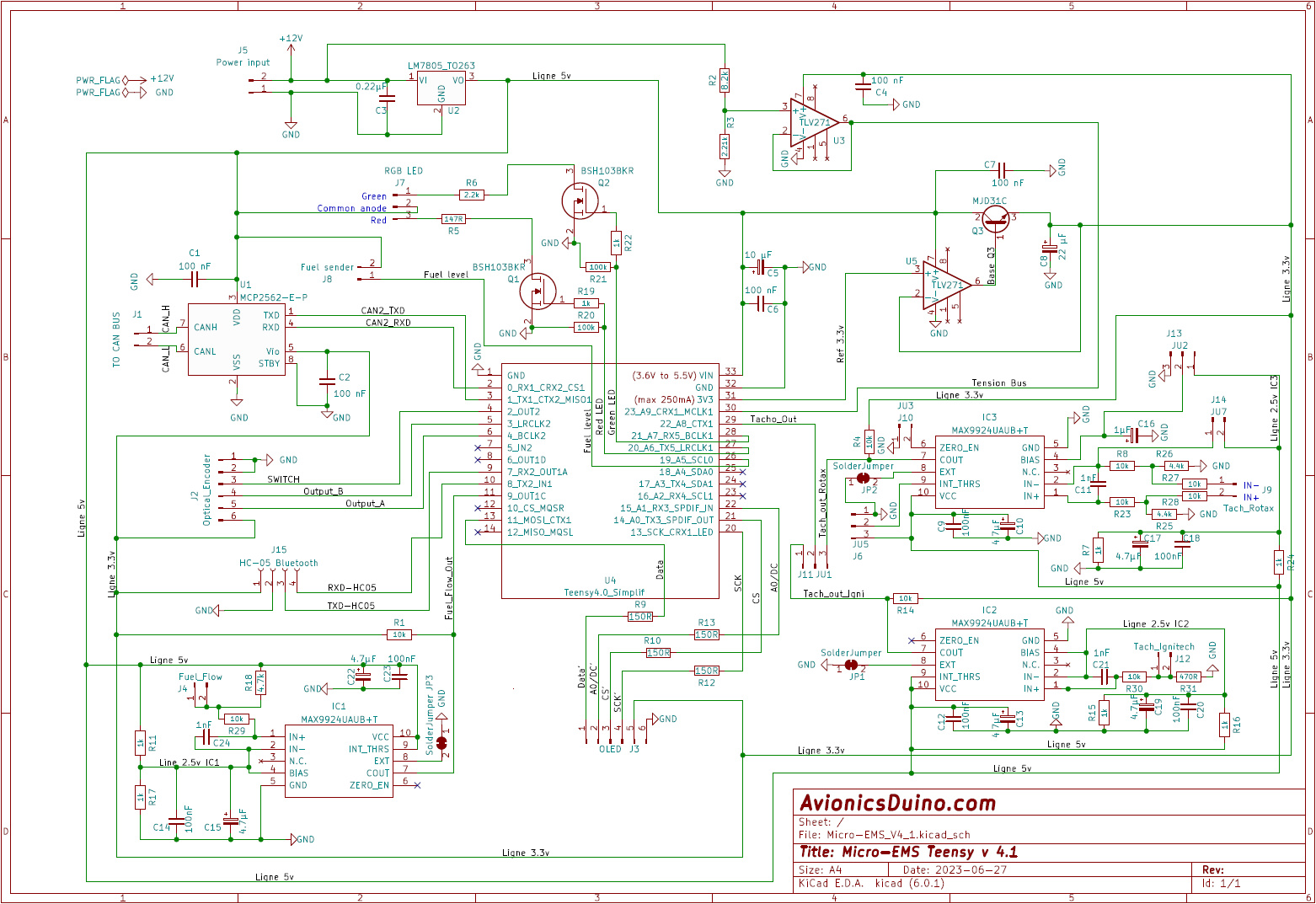
Teensy Micro-EMS schematics
Figure 9 shows the schematics (hover the mouse pointer over the image to enlarge it). The system’s “brain” is a Teensy 4.0 board.
5 volts power supply
The 5-volt source is an LM7805 linear regulator (U2). The current of approximately 200 mA drawn by the Micro-EMS, coupled with the significant voltage drop from 13.7 volts (with a running engine) to 5 volts, leads to substantial heating of this regulator, requiring adequate heatsinking. There are thermal vias under the LM7805 to facilitate thermal transfer to the PCB ground plane and a large aluminum spacer with thermal paste between the PCB and the case to transfer heat from the PCB to the aluminum case.
3.3 volts power supply
The 3.3-volt output of the Teensy board could be insufficient on its own due to the load of the circuits to be powered. Therefore, a buffer has been added to obtain the needed current without running any risk of a drop in the 3.3-volt reference voltage. Such a drop could disturb specific analog measurements. This buffer consists of an operational amplifier (U5) and a transistor (Q3).
Battery voltage measurement
The voltage is first lowered by an appropriate voltage divider (R2 and R3) and then transmitted to the Teensy analog pin A9 via the operational amplifier U3 set up in the voltage follower configuration to protect A9 and match the impedances.
Variable reluctance sensor signal conditioning
The high voltage analog signal from the Rotax variable reluctance sensor is processed by the specialized MAX9924 circuit (IC3), ensuring noise suppression and conversion to a square signal of 3.3 volts of amplitude with identical frequency. See the page on variable reluctance sensors and signal conditioning, where the operation of the MAX9924 is explained in detail. The output signal from IC3 is applied via selector J11-JU1 to Teensy digital input pin 22, the only pin usable with the FreqMeasure library, which measures the signal period.
Electronic ignition unit tacho output signal conditioning
The noisy roughly square signal of approximately 15 volts in amplitude from the Tacho output of the Ignitech electronic ignition unit is processed by a second MAX9924 (IC2) to eliminate noise and ensure conversion to a digital signal of 3.3 volts of amplitude, also applied to the Teensy digital input pin 22, via the J11-JU1 selector.
Fuel flow sensor signal conditioning
A third MAX9924 (IC1) processes the fuel flow sensor signal. The 10k resistor R1 is a pull-up resistor for the open-drain output of the MAX9924. Resistor R18 (4.7k) is the pull-up resistor for the open-collector output of the Red Cube FT-60 flow sensor. The COUT output of the MAX9924 is connected to digital input pin 9 of the Teensy board, the only pin usable with the FreqCount library, which counts the pulses.
Idiot lamp
The Q1 and Q2 MOSFET transistors are configured as switches for the RGB diode used as an idiot lamp. This LED draws a current higher (especially for the red color) than 4 mA, the maximum continuous current recommended for any digital outputs of the Teensy 4.1 board.
CAN transceiver
The CAN transceiver MCP2562 (U1) is connected to the CAN2 controller output of the Teensy board (pins 0 and 1).
OLED Display
The Adafruit OLED 1.5″ 128×128 pixel display with SSD1327 controller (Product ID: 4741) is connected to an SPI bus of the Teensy board. A 150-ohm resistor is inserted in series in each of the 4 SPI lines to reduce the high-frequency harmonics generated by the SPI signals, minimizing the potential risk of electromagnetic interferences with the aircraft radio equipment.
Bluetooth module
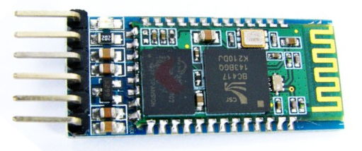
Commercially available HC-05 Bluetooth modules have 6 pins (fig. 10), and the two outermost pins are used for configuration (for example, to change the module name or password). The reader is invited to consult one of the countless tutorials available on the Internet for this configuration.
Once setup is complete, only the center 4 pins are used for mounting on the PCB. These four pins must be soldered perpendicular to the module and not in the axis as on all new modules. Therefore, it is necessary to remove the original 6-pin connector. To do this, you must start by cutting the pins and carefully removing the black insulation plastic using a mini Dremel grinder. Then, individually desolder the remaining pin segments with a soldering/desoldering station, and finally, clean the PCB holes with desoldering braid.
When the micro-EMS is in operation, it transmits its parameters constantly over Bluetooth classic. To save them, pair an Android smartphone or tablet and use the “Serial Bluetooth Terminal” program from Kai Morich.
Flight test results
The battery voltage is always within ±0.05 volts compared to a reference measurement made with a Fluke 115 multimeter. The idiot lamp LED is excellently visible, even in direct sunlight.
The RPM is the same ±10 rpm as the tachometer of the propeller constant speed controller (Smart Avionics CSC-1/P) acting as a reference, regardless of the input selected by the jumper on J11.
The fuel calculator works as expected. The display is very stable. At the end of long flights, the remaining fuel levels, either calculated by the micro-EMS or measured manually in the tank (with a perfectly calibrated wooden fuel tank measuring stick), never differ by more than ±1 liter. This level is always within the interval of 3 to 4 liters the Wema probe provides, and this interval is always consistent with the systematic check with the wooden stick before and at the end of each flight.
It took a few flights of more than one hour each to adjust the K factor, according to the formula Kadjusted = Kcurrent x Calculated fuel amount used/Measured fuel amount used. The retained K factor is 21000 pulses for one liter, whereas the theoretical K factor of the Red Cube is close to 18000.
With the Arduino version of the Micro-EMS as well as with a previous MGL Stratomaster FF1 fuel computer (and with the same Red Cube), we also obtained a K factor higher than the expected K factor, which could suggest supernumerary pulses related to the vibrations and the rigid installation of the Red Cube on the firewall. The sensor manufacturer recommends a flexible installation between two hoses instead.
Hi Robert,
I moved your comment from the home page to the Teensy Micro-EMS page.
Your first question makes perfect sense. Most of the answers can be found on the variable reluctance (VR) sensor page. I suggest you carefully read (or re-read) that somewhat complex page. The Teensy Micro-EMS can handle both single-ended and differential VR sensors; jumpers are used to configure the setup. The Rotax tachometer VR sensor is a differential type. However, on my aircraft, the constant-speed propeller controller is designed for a single-ended VR sensor, so I had to ground one of the sensor’s output wires, effectively converting it to single-ended operation (it doesn’t matter which wire is grounded). Consequently, the Rotax tachometer input stage on my Teensy Micro-EMS is configured for a single-ended VR sensor, meaning I use only one wire for this sensor on the DB9 connector. If you want to configure the Micro-EMS for a two-wire differential VR sensor, the DB9 connector won’t have enough pins, so you would need to use a DB15 connector instead, or use the pin designated for the Ignitech ignition unit if you don’t need it.
Regarding your second question, I think your idea is entirely feasible. The float-type fuel level sensor will only indicate fuel quantities between 0 and 37 liters (staying capped at 37 above that level), but the fuel flow meter will provide a fairly accurate calculated reading (within one liter) provided the K-factor is correctly calibrated based on actual fuel consumption. Of course, you need a way to accurately measure the fuel level in the tank while on the ground, such as with a wooden dipstick. Naturally, lines 113 and 114 of the program will need to be adjusted to match your specific float-type fuel sender.
Benjamin
Hi Benjamin,
thanks for the prompt reply.
Yes, I have questions, but right now I am finishing the Teenie Micro EMS. In the shielded area there is the connector for the rotax ignotion Input with 2 terminals. Rotax ignition+ and Rotax ignition -. One the db9 outgoing there is only 1 terminal.
Which wire ends there and what happens to the other one?
Second, in my plane (Pioneer 200) the fuel gauge is fed by a float with a Potentiometer, because of mechanical limitations that indicates only from Zero to 37 l, as the fuel Tank holds up to 54 l i’d like to calculate the first 17 l just with the fuel flow and from 37 l in more precise with fuel flow and fuel sensor.
Do you think that is feasable?
Robert