Resistance measurement: last updated by Gabriel on Octobre 13, 2022)
This page deals with aircraft engine sensors whose electrical resistance varies with temperature or pressure.
The EMS (Engine Monitoring System) will therefore have to measure these resistances before referring to the characteristic curve of the sensor to calculate and display the measured variable.
The method is to supply a reference voltage Vref to a voltage divider consisting of a fixed resistor R in series with the variable resistance sensor Rsensor (Fig.1).
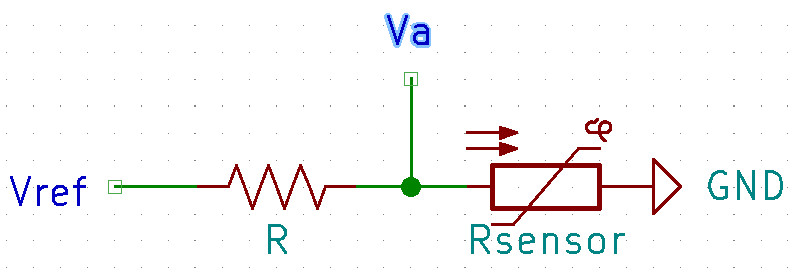
The divider produces an output voltage Va which allows the sensor resistance calculation. The relationship between Rsensor and Va is as follows:
Rsensor = R Va / (Vref – Va)
An Analog-to-Digital Converter (ADC) included in the microcontroller is used to measure Va. The sensor resistance is then calculated using the above formula.
However, a few precautions should be taken, which we detail below.
Reference voltage Vref
There are two basic requirements. Firstly, suppose the sensor gets disconnected from the voltage divider (broken sensor wire, for example). In that case, the microcontroller’s analog input pin is exposed to Vref, which must, therefore, not be higher than what is supported by the microcontroller, i.e., 5V for Arduino and 3.3V for Teensy.
Secondly, to make precise measurements, the voltage Vref must be stable, whatever the load, and strictly equal to the ADC reference voltage.
Teensy boards can be powered with a 5V source applied to its Vin pin but operate at 3.3V. The ADC reference voltage is 3.3V. There is a 3.3V output pin, but the maximum load is 250 mA.
This 3.3V output could supply the voltage divider bridges, but its voltage drops significantly with the load. Furthermore, all voltage divider bridges could draw more than 250 mA.
Therefore, we designed the circuit shown in figure 2 to comply with these requirements.
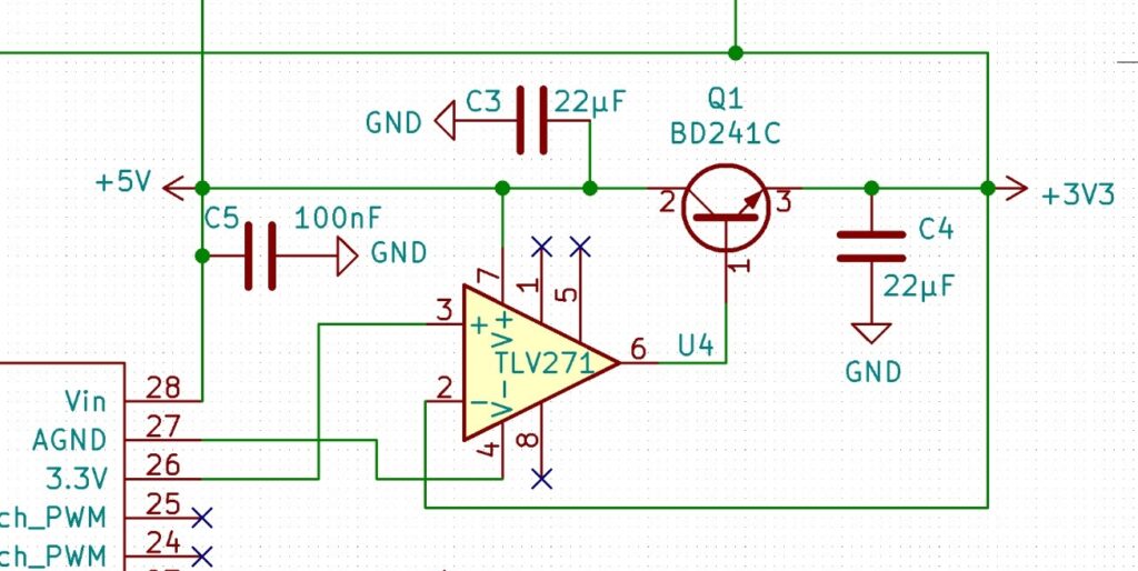
This schematics is based on a general-purpose TLV271 operational amplifier (Op-Amp) configured as a voltage follower with a current buffering circuit using a BD241 NPN power bipolar junction transistor (BJT). In this negative-feedback configuration, the op-amp automatically generates whatever output voltage is needed to make the BJT’s emitter voltage equal to the input voltage (Reference here).
In this way, a very stable voltage Vref is obtained, strictly equal to the 3.3V output of the Teensy, which is used as a reference by the ADC, and not limited to 250 mA.
Measurement range adjustment
To maximize measurement accuracy, it is advisable to ensure that the voltage analyzed by the ADC covers most of the 0V – 3.3V range. Certain precautions are therefore necessary to fulfill this condition.
Consider the case of a VDO-150 temperature sensor. Its resistance (Rsensor) range extends from 23 Ohm at 140°C to 353 Ohm at 50°C.
The resistor R maximizing the voltage range Va at the divider output must first be selected. It is easily calculated that in the E24 series of resistors, it is R = 91 Ohms.
According to Ohm’s law, the divider output voltage Va will vary from 0.67V to 2.62V, i.e., a range of 1.95V. This only covers 59% of the ADC measurement range. To improve this:
- An offset to decrease the low limit (here 0.67V) close to zero (say 0.1V) can be applied.
- And the signal can then be amplified so that the high limit (here 2.62-0.67=1.95V) becomes close to 3.3V (say 3.2V).
These two objectives are achieved with the following diagram (Fig.3)
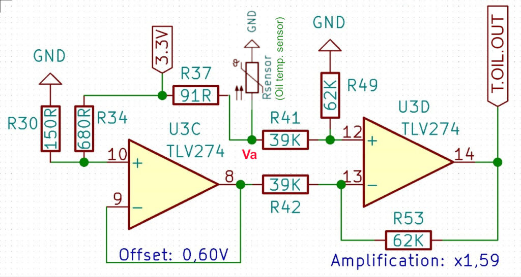
The desired offset is created by the R30/R34 divider whose output voltage is equal to 3.3 x R30/(R30+R34), i.e., 0.6 volts. This offset is then stabilized by the first op-amp U3C configured as a voltage follower. The output voltage Va of the R37/Rsensor divider and the offset (output of U3C) are then processed by the second op-amp U3D, configured as a differential amplifier or voltage subtractor. The differential amplifier amplifies the voltage difference between its inverting and non-inverting inputs. This op-amp amplifies the difference Va – Offset to reach the 3.2V high limit. The gain K of U3D equals R53/R42 or R49/R41, which is 1.59.
So for Va = 0.67V, U3D Vout (T.OIL.OUT) becomes:
(0.67-0.60) x 1.59 = 0.11 V
And for Va = 2.62V, U3D Vout becomes:
(2.62-0.60) x 1.59 = 3.21 V
It could be objected that this design requires some hardware resources because two AOPs and a few resistors are needed per analog channel. We consider this the price to pay for stable and accurate measurements. Four-channel SMD AOPs are commonly used to save space; the TLV274 is a good example.
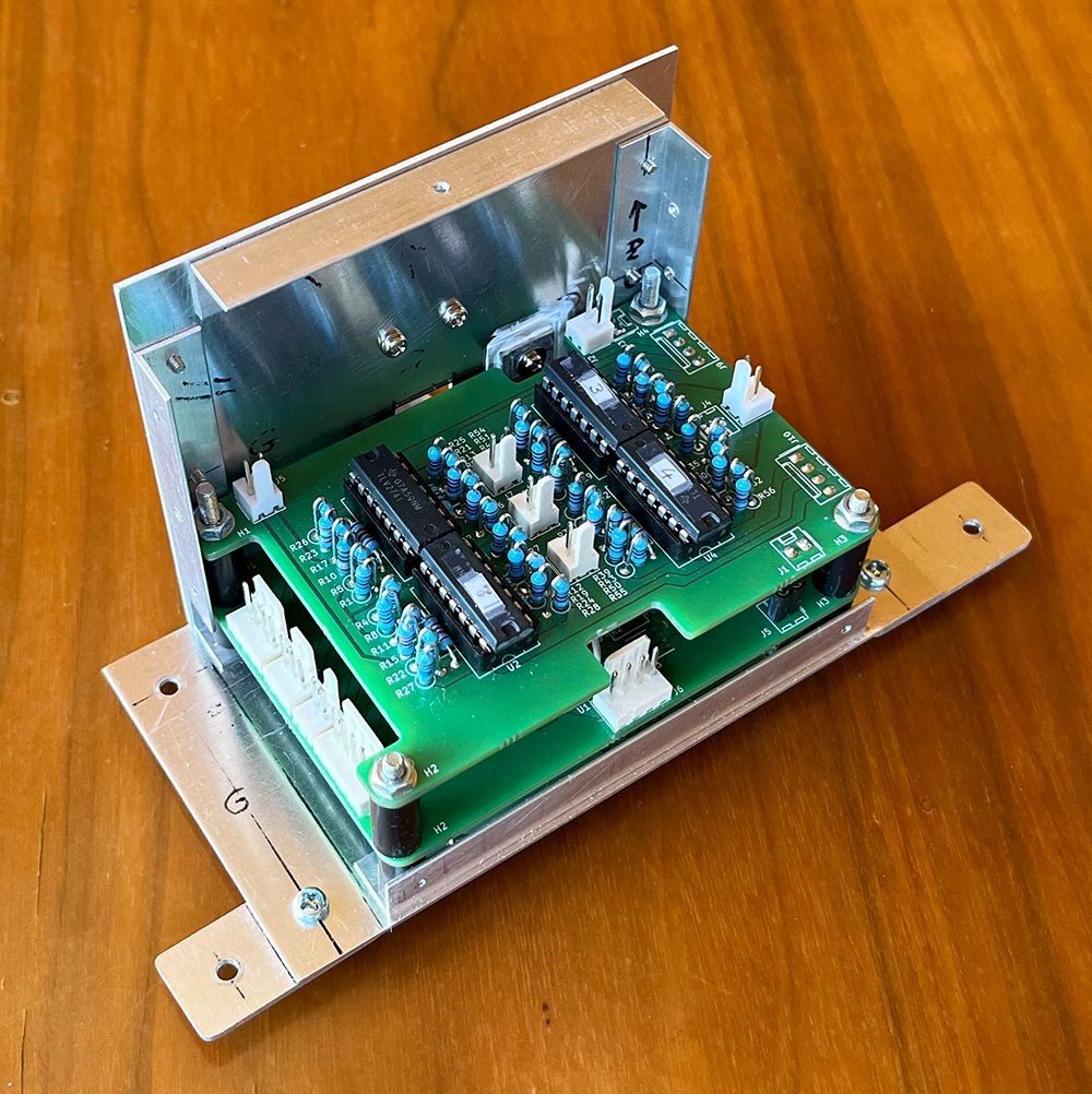
Figure 4 shows the analog section of an EMS prototype (the digital section and the microcontroller are underneath), which processes eight sensor signals with standard through-hole components on a 58 x 88 mm PCB. Four 4-channel Op amps are used, i.e., 16 op-amps.
Calculation of the measured variable
With Vref = 3.3 volts, the microcontroller can then successively:
- Calculate Vout from the 10-bit ADC output:
Vout = Vref * ADCOutput/1023
- Calculate Va:
Va = (Vout + K*Offset)/K
- Calculate the sensor resistance:
Rsensor = R * Va / (Vref – Va)
- Calculate the measured variable. In this example, T is an oil temperature described by the formula:
T = A * Log(Rsensor)2 + B * Log(Rsensor) + C
(see the Rotax temperature sensors page)
Precautions regarding the choice of the resistors
It should be noted that the above calculations may lead to significant errors if resistors with a tolerance as low as 1% are used.
Depending on the desired accuracy, we can:
- Either do nothing if an error of several percent can be tolerated.
- Or calibrate the final assembly and adjust the coefficients of the above formulas (for example, the offset and the amplification coefficient) to obtain the correct value of the measured quantity .
- Either select resistors with 0.1% tolerance, which avoids the above calibration.