(CAN bus: Last updated by Benjamin on January 30, 2025)
The CAN (Controller Area Network) bus is based on a bidirectional, asynchronous, half-duplex serial protocol. There is no clock signal wire; all connected devices must rely on implicit synchronization with the same baud rate. Only one device can transmit at a time, provided that the bus is free.
This page is not intended to provide an exhaustive theoretical description of CAN but to explain some basic notions to help the reader (amateur aircraft builder, pilot, or hobbyist) carry out a simple implementation within the framework of a personal avionics project.
The CAN bus implements an approach known as multiplexing. The same cable (the bus) connects several devices or nodes (control units, sensors, etc.), which communicate in turn. The physical layer of the CAN protocol consists of the bus itself (two wires transmitting the data) and all the controllers (one per node; see below what a CAN controller is).
This technique eliminates the need to wire dedicated lines for each piece of information to be transmitted, as is the case in a point-to-point connection, such as UART or RS232.
The bus
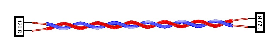
The CAN bus is made up of a twisted pair (shielded or not) terminated at each end with a 120 ohm resistor, as below (fig. 1):
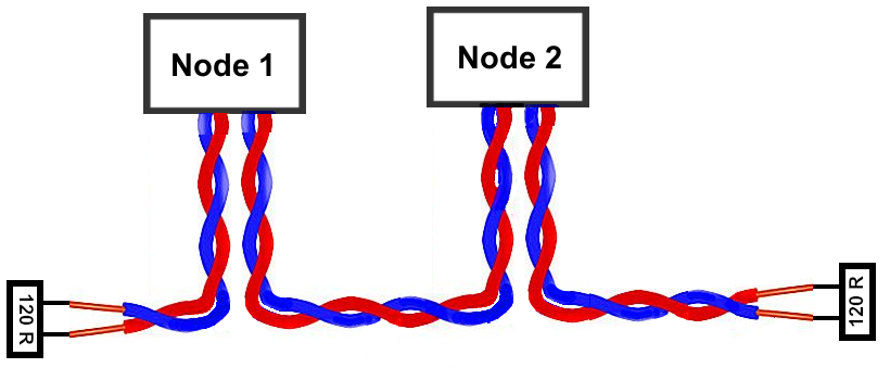
Each node may be connected to the bus via a twisted pair (shielded or not) (fig. 2). However, the length of this T connection must be as short as possible, a maximum of 30 cm. The bus itself can extend linearly for several tens of meters or more. The length, however, reduces the maximum speed of the bus. The CAN bus has a linear topology. A star topology should be avoided.
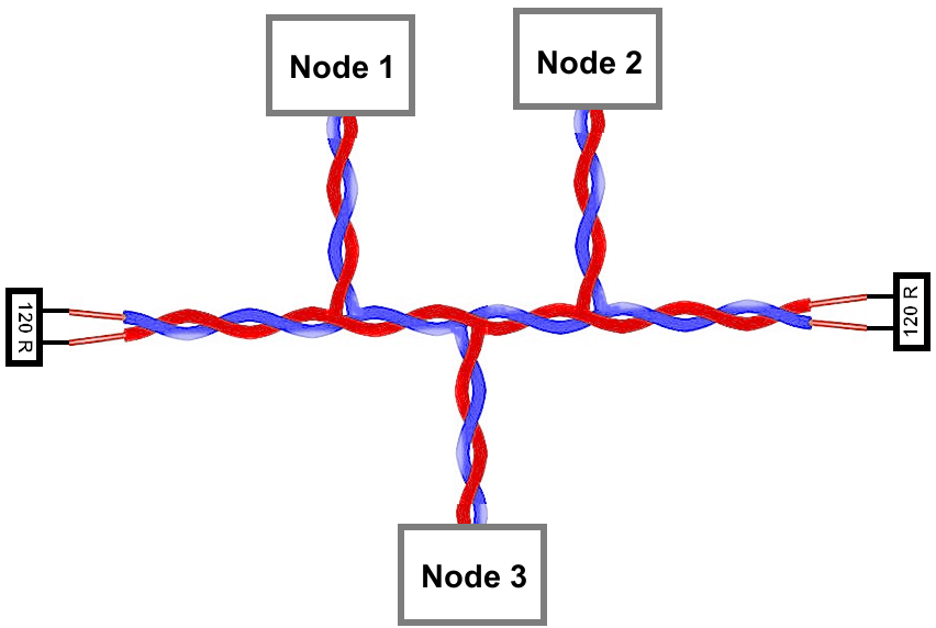
If the distance from a node to the bus might exceed 30 cm, it would then be better to adopt a configuration according to Figure 3 below.
Disconnecting a node must never interrupt the continuity of the bus, which must be able to continue to operate normally.
The CAN bus conveys the data using a differential signaling scheme. Information is transmitted as the difference between the voltages of the two wires, namely CAN H and CAN L. This technique ensures excellent immunity to electromagnetic disturbances: as the disturbances equally affect both wires, the voltage between them remains the same.
Controllers and their roles
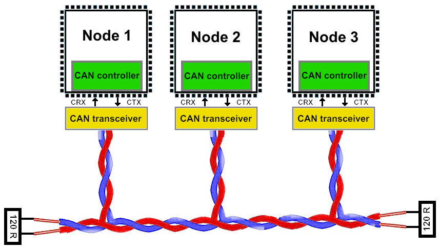
Each node of a CAN bus includes, in addition to its sensors or other actuators, a microcontroller, a CAN controller, and a CAN transceiver (see Figure 5 below). Recent 32-bit microcontrollers like those fitted to Teensy boards integrate one or more CAN controllers. However, a transceiver must be added to connect them to a CAN bus (see below). The ATmega328P microcontroller on 8-bit Arduino boards, like the UNO Rev3 board, does not include a CAN controller, so an external controller AND a transceiver must be added.
All nodes connected to the bus have the same rights. There is neither master nor slave. The protocol governing message exchanges is hard-coded in the controller. It is based on the broadcasting principle, which involves simultaneously sending messages to all recipients. During transmissions, no station is addressed in particular.
Each message includes an identifier field. The identifier is not a source or destination address but rather a label indicating both the message’s content and its priority. All nodes constantly listen to the bus and receive all messages. Based on the identifier, each node decides whether to ignore the data or accept and process it. The programmer determines the identifiers when programming the nodes.
An arbitration system is essential. To be processed in real-time, the information must not only be transmitted quickly (which requires a physical channel allowing high throughput, up to 1 Mbit/s) but also the assignment of the bus to a priority node must be immediate if several nodes wish to transmit messages simultaneously.
The priority of the information exchanged on the bus can be very diverse. A rapidly varying parameter, such as the state of a sensor or the control of a motor, must be transmitted more frequently, with higher priority, and with less delay than a slowly changing value, such as engine temperature.
On a CAN network, each message’s identifier, which is a sequence of 11 bits (standard format) or 29 bits (extended format), determines its priority. The programmer assigns priorities during the software design. The lower the binary value of the identifier, the higher the message’s priority.
Nodes attempting to transmit simultaneously on the bus compare their message identifier with that of competing messages. Messages with lower priority lose the competition against those with higher priority. When a node loses the competition, it stops transmitting. It then automatically becomes a simple receiver of the message and only attempts to send its message again when the bus becomes free.
This priority management is entirely transparent for the programmer, who does not have to worry about it except when choosing identifiers. It is wholly ensured by the protocol contained in each node’s CAN controller so that each message is ultimately always sent, and no information is ever lost.
Message structure
This page only covers the standard CAN protocol, which is limited to a data field of up to 8 bytes and a maximum rate of 1 Mbit/s. The more recent CAN FD (Flexible Data rate) allows messages of up to 64 bytes of data with a maximum rate of 2 Mbit/s and uses the same principles.
The standard CAN protocol has two versions: CAN 2.0A, which has an 11-bit identification field, and CAN 2.0B, which has an identifier comprising 18 additional bits, therefore 29 bits. Version 2.0B is known as extended CAN. The structure of the frames is shown below (fig. 4).
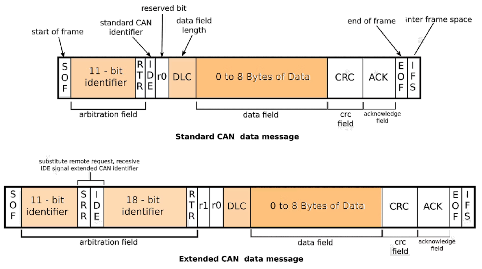
A frame contains the following fields:
- Field (number of bits) Description
- SOF (1) Start Of Frame. Marks the start of a message.
- Identifier (11) CAN 11-bit identifier data field
- RTR (1) Remote Transmission Request. Low when information is requested by another node.
- IDE (1) Identifier Extension bit: indicates standard or extended CAN identifier.
- R0 (1) Reserved for future use.
- DLC (4) Data Length Code: number of bytes in the transmission.
- Data (0 – 64) Data being transmitted.
- CRC (16) The 16-bit (15 bits plus delimiter) cyclic redundancy check (CRC) contains the checksum (number of bits transmitted) of the preceding application data for transmitting error detection.
- ACK (2) When a node successfully receives a message, it ACKnowledges it by overwriting this bit with a LOW bit. On the other hand, if a node finds an error in a message, it allows this bit to remain HIGH and ignores the message.
- EOF (7) End Of Frame is a 7-bit field that denotes the end of every CAN frame (message).
- IFS (3+) Inter Frame Space (IFS) is the time that the controller needs to move a frame (message) into position in the buffer area. Note that IFS contains a minimum of three consecutive recessive (1) bits. After three recessive bits have passed, when a dominant bit is detected, it becomes the SOF bit of the next frame.
With an 11-bit identifier and an 8-byte message, the theoretical message length is 108 bits. But it is necessary to take into account bit stuffing. The stuffing is needed because CAN is an asynchronous bus, and it needs a falling or rising edge every five bits for clock resynchronization. Bit stuffing consists of the transmitter inserting a bit of the opposite value after five consecutive bits of the same value if that frame has more than five consecutive bits of the same value. This means that the length of a message can reach almost 130 bits. This must be taken into account when calculating the bus load and determining whether this load is compatible with the bus baud rate.
CAN controllers that support the extended format can also send and receive messages in the standard format. However, if some controllers on the network only support the standard format, the extended messages will be misinterpreted.
The CAN controllers of the Teensy boards used in the AvionicsDuino project support the extended format. Given the modest requirements of the project, only the standard format is used, therefore, with 11-bit identifiers. This allows the use of 2048 different identifiers, a more than sufficient number.
Security and reliability
The CAN protocol integrates error detection and management mechanisms. All nodes in the network monitor the bus simultaneously. They immediately detect differences between bits received and bits transmitted. As soon as an error is detected, the current transmission is interrupted by issuing an Error Flag. Therefore, the transmitter must start sending its message again.
This error-handling system is transparent for both the developer and the user. It automatically manages conflicts and errors by issuing error frames to inform the message sender about the type of error encountered. A node can even distinguish between temporary disturbances and permanent faults. Nodes with a permanent fault are automatically disconnected from the network. Thus, the probability that an error remains undetected is less than 4.7 x 10⁻¹¹.
The power, robustness, and efficiency of the CAN bus are linked to the protocol’s rigorous management of errors and priorities, which is hardcoded in the CAN controllers of each node, and to the immunity to electromagnetic interference of twisted pairs carrying a differential signal.
Controllers and transceivers
The whole complexity of the protocol is thus managed by a specialized electronic circuit, the CAN controller (or driver). As already mentioned above, the 8-bit microcontroller of the Arduino Uno, Nano, and Mega boards does not include a CAN driver. If we want to connect these boards to a CAN bus, we must add an external module, generally connected via I2C or SPI. This module is most often equipped with the MCP2515 CAN bus controller circuit, associated with varying transceivers, depending on the module, MCP2551, MCP2562, TJA1050, SN65HVD1050… etc.
The transceiver converts the TTL/CMOS signals generated by the CAN controller into differential signals that convey information on the CAN_H and CAN_L pair constituting the CAN bus. The 32-bit microcontrollers of the Teensy 4.x boards used in the AvionicsDuino project include several CAN controllers. If you want to use several CAN controllers from the same microcontroller, you must add a transceiver to each one.
Therefore, each node on a CAN bus (in addition to its own sensors, actuators, displays, or other particular devices) includes a microcontroller, a CAN controller, and a CAN transceiver (Fig. 5).
Cables and connectors
The practical realization of the bus is poorly documented: which cables, which connectors? The designer has a certain freedom; only the notion of twisted pairs is well established and must be scrupulously respected. Unless you decide to respect stricter standards such as those set out by CANAerospace (see below).
We use a cable consisting of a ground wire and two individually shielded twisted pairs (Ref. Belden 8723, fig. 6). Unfortunately, this light, robust, and easy-to-connect cable is quite expensive. You can also use an Ethernet cable, which is much more common and less expensive but less easy to connect due to the very small diameter of the wires. The red-black pair of the Belden cable is used (if necessary) to power the nodes, and the white-green pair constitutes the CAN bus.
The nodes are all supposed to share a common ground in the aircraft, possibly via the black wire. The non-insulated ground wire allows all shields to be connected to the ground but at only one end or one point of the bus: no current must pass through it to avoid the effects of ground loops. Its continuity must be ensured in the node connectors. This non-insulated ground wire must not be used for any other purpose.

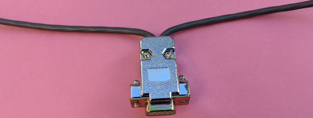
The usual CAN connector is a SUB-D9 (fig. 7). Pins 7 and 2 are dedicated to CAN H and CAN L signals, and pins 3 and 6 are dedicated to ground. If necessary, an external power supply can be connected to pin 9. The bus shield is connected to pin 5 of a single node, which must ensure the whole shielding’s single grounding point. In specific contexts, pins may vary.

There is no standard, cost-effective T-connector to reliably connect a cable from a node to the bus itself. We saw above that such a cable must be as short as possible when it cannot be avoided. Therefore, it is clearly preferable to divert the bus towards a node rather than excessively lengthening a T-connection (see Figure 3). The SUB-D connector is then inserted into the bus itself (fig. 8).
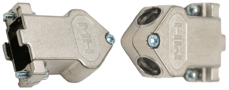
A dual-entry SUB-D9 die-cast hood like the one in Figure 9 (MH Connectors Ref. MHDU45ZK9-K) provides more room for connections. The cable wires entering each side of the cover are linked together according to their color and connected to the corresponding pins of the SUB-D connector, so that the bus crosses this connection without being interrupted. The node can be removed without disrupting the operation of the bus. When the node is connected, it is directly on the bus, which complies with the short connection requirement mentioned above.
The software
The CAN controller manages the protocol, which is the most complex task. The programmer’s role will essentially be to decide on the ID assignments to network messages according to their priorities and to program the microcontroller of each node, mainly so the node reacts appropriately depending on the context: sending a message to the network when its sensors provide it with new information, listening and sorting network messages to respond adequately or initiate a particular action.
The programmer can use numerous generic libraries, which are more or less dedicated to certain CAN controllers. In the Teensy world, specifically Teensy 4.x, a commonly used library is Flexcan_t4.
This library fully exploits the numerous possibilities offered by the CAN controllers of the iMXRT1062 microcontrollers of the Teensy 4.x boards. In particular, it manages reception buffers, mailboxes, and filtering mechanisms, which allow controllers to only accept messages that concern them and ignore others without having to process them. In practice, only a small part of this library’s functionality is used for our basic needs.
The reader can refer to the various AvionicsDuino software; they all contain examples of using this library.
CANaerospace
CANaerospace is an open-source project developed by Stock Flight Systems. It describes a standardized set of protocols and data formats designed to ensure highly reliable communication between aeronautical computer systems via the Controller Area Network (CAN).
Reading this presentation is very informative. The concept of IMA (Integrated Modular Avionics Concept) is well described.
The AvionicsDuino project CAN bus
The requirements are modest. It only involves connecting four, five, or six nodes, which exchange a few messages between them at moderate frequencies between 5 and 20 Hz. No filtering technique is used. All nodes read the ID of all messages transmitted to the bus and only decode the information that concerns them. We did not seek to satisfy the constraints and recommendations of the CANaerospace protocol, which are disproportionate to our project.
First CAN bus configuration
Figure 10 below shows the CAN bus architecture as it was initially implemented in one of the aircraft participating in the AvionicsDuino project. There were only 4 knots. Indeed, for historical reasons, the AHRS module was still connected to the main unit of the EFIS by a serial UART connection.
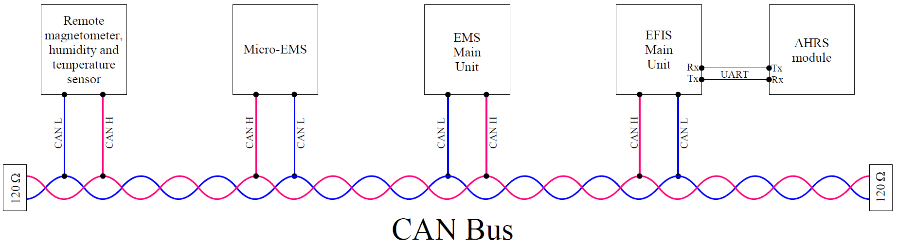
The table below (fig. 11) summarizes the data exchanges on this aircraft’s CAN bus in this first configuration. The bus speed was set at 0.5 Mbit/s. The networked elements were the EFIS main unit, the magnetometer remote module, the EMS main unit, and the micro-EMS.
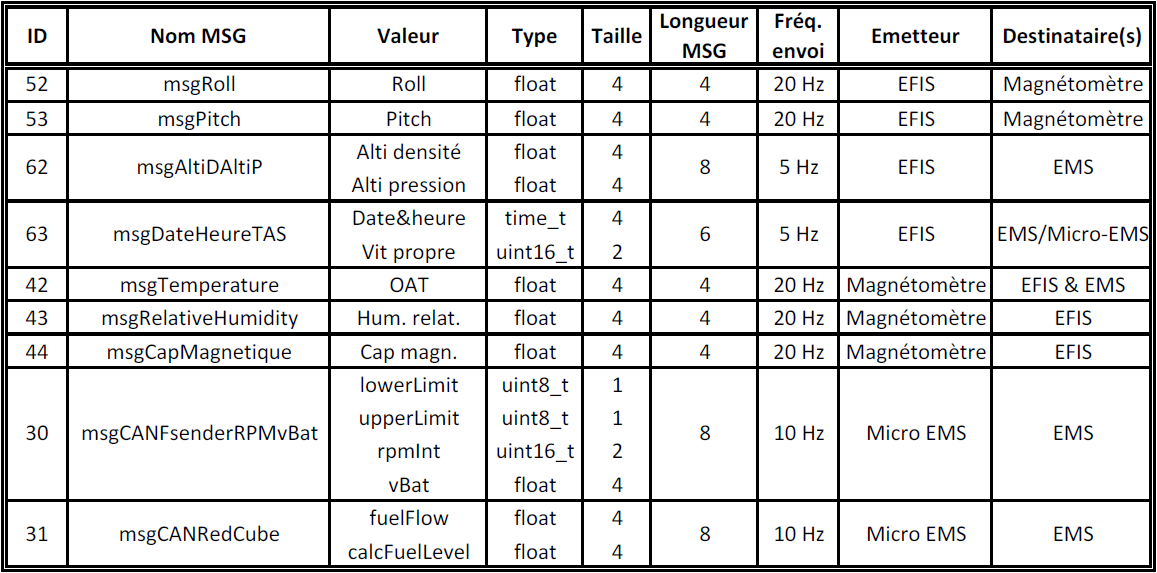
In this first configuration, when estimating total message lengths to 130 bits (for 8 bytes of data), 115 bits (for 6 bytes), and 100 bits (for 4 bytes), and taking into account the sending frequencies, we can calculate a high estimate of the bus load at 13.825 Kbit/s, or only 2.7% of the maximum bus bandwidth. So, we are very far from the risk area of data loss!
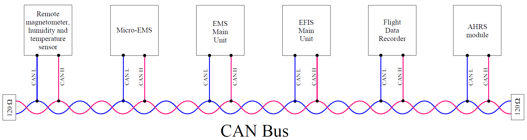
Second CAN bus configuration
Figure 12 below shows the current CAN bus architecture in the same aircraft. Six nodes are connected to the bus, which is still very few compared to the hundred nodes in modern cars, often distributed over several buses. The old UART connection between the EFIS main unit and the AHRS has been removed. A new Flight Data Recorder (FDR) has appeared, its hardware design is completed, and the first test flights have been successful. It is based on an ESP32 module coupled to a micro-SD card reader. A substantial update of the Flight Data Recorder page has been made; it will be completed as soon as the final developments of the software for this recorder are completed.
The table below (fig. 13) summarizes the data exchanges on the CAN bus in this second configuration. The bus speed is still 0.5 Mbit/s.
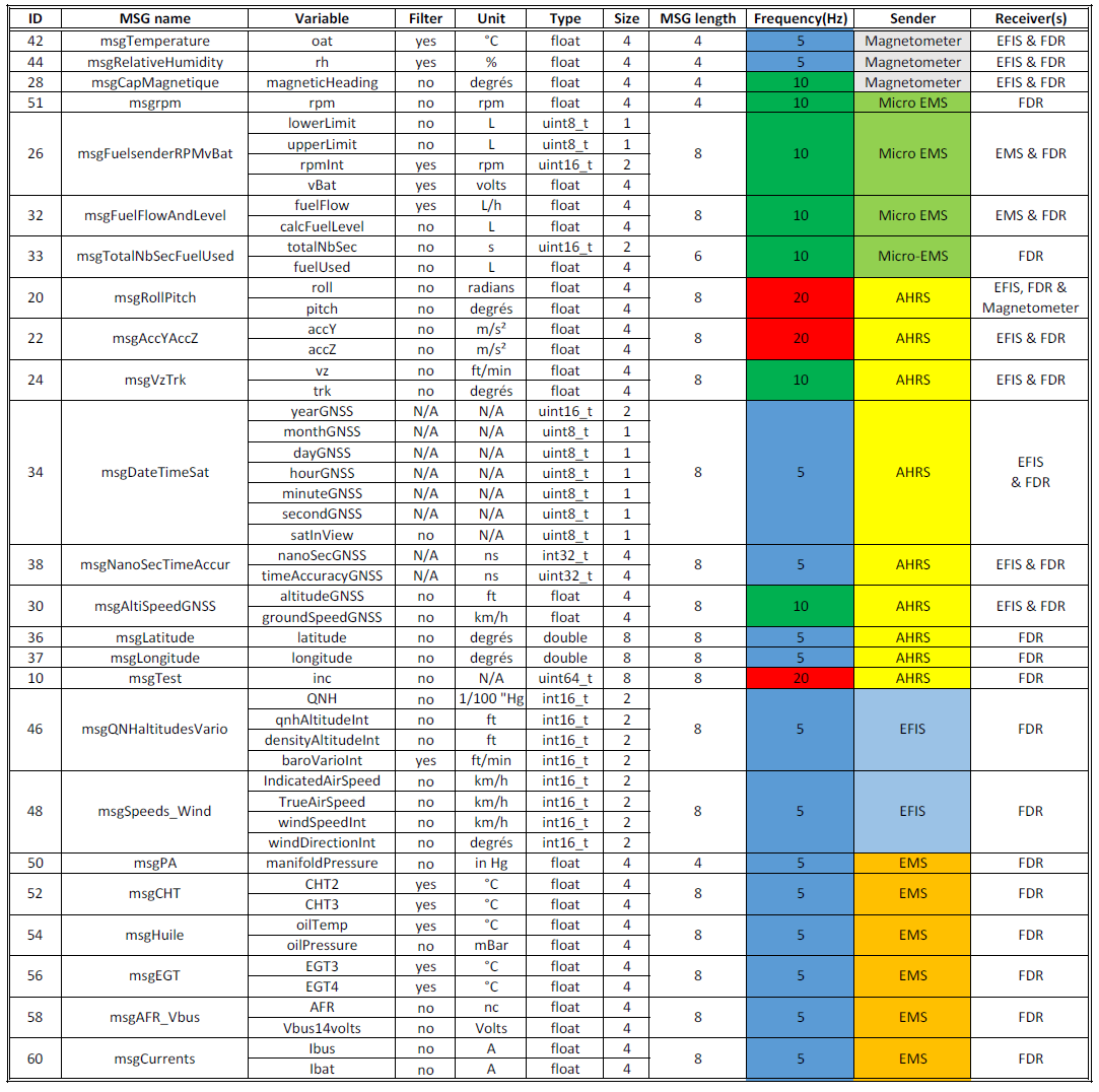
In this second configuration, the number of messages sent on the bus has increased significantly. Most of them have a data load of 8 bytes, all of which are intended for the FDR, and many of which are intended only for the FDR. The role of the FDR is, of course, to record all the CAN bus traffic and, through it, many flight, environment, and engine parameters. A high estimate of the bus load is calculated at 23.65 Kbps, which is only 4.7% of the maximum possible load given the bus speed.
Software compatible with these two CAN bus configurations can be downloaded from GitHub. It is obviously important not to mix them up. The new FDR software will not be compatible with the first configuration software. Please read carefully the README files on GitHub; they detail the software version and their compatibilities.
Excellent information. Thank you.