(Exhaust Gaz Temperature (EGT) measurement: Last updated by Benjamin on October 19,2022)
The Exhaust Gas Temperature (EGT) is one of the many parameters to consider when monitoring an aircraft engine’s operation. This temperature correlates to the air-fuel ratio (AFR) of the mixture introduced into the cylinders. The ideal air-fuel ratio is the one that ensures complete combustion. It is also the one that results in the maximum temperature of exhaust gases. A decrease in exhaust gas temperature is observed with a leaner or richer mixture compared to this ideal ratio. It is not our purpose here to discuss the interest, or otherwise, of EGT monitoring; the experts themselves may have divergent opinions on this subject. We will only present the measurement technique.
Thermocouples
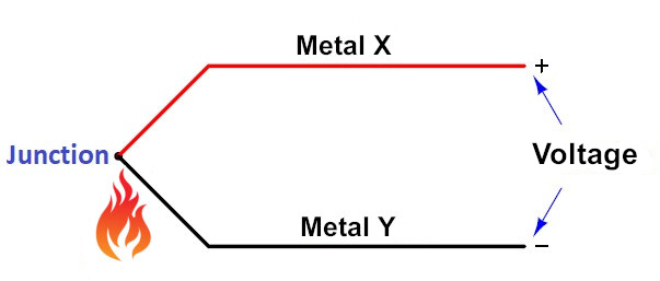
Given the temperatures to be evaluated, which can approach 900°C, the sensors used are thermocouples. The very simplified working principle of thermocouples is as follows: by heating the junction of two different metals, a voltage appears between their unjoined ends (fig. 1). This is called the thermoelectric effect. All pairs of dissimilar metals exhibit this effect.
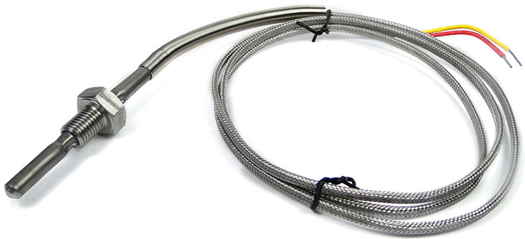
There are many types of thermocouples, depending on the metals used. The ones that interest us here are type K thermocouples (fig. 2), where the metals used are Chromel and Alumel. They can assess temperatures up to more than 1300°C. The voltage generated is very low, around 40µV/degree C, with an almost linear response between 0°C and 1000°C, therefore almost proportional to the temperature. Such a low output voltage makes thermocouples particularly susceptible to electromagnetic interference, hence the importance of shielding in the form of a metal braid protecting the wires. The thermocouples we use are available here.
Thermocouple amplifiers
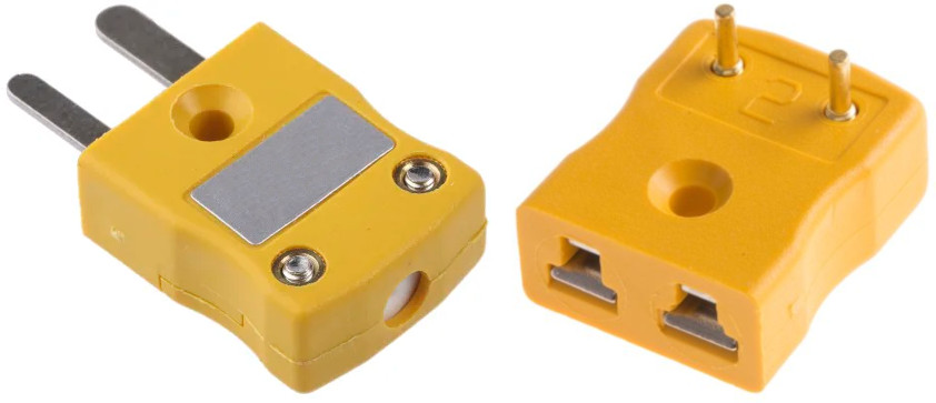
Analog-to-digital converters cannot directly measure the very low voltages generated by thermocouples. Therefore, amplification is necessary. Thermocouple amplifiers also correct linearity errors as well. In addition, the amplifier circuit must also consider the junctions between the connectors (generally made of copper) and the Chromel and Alumel wires. These junctions (called cold junctions) also behave like thermocouples and generate parasitic voltages. This is called cold junction compensation. To make this compensation, the thermocouple amplifier integrates a temperature sensor that measures the temperature of the cold junctions. These must therefore be placed close to the amplifier. Chromel-copper and Alumel copper cold junctions require specific connectors (fig. 3).
Thermocouple amplifiers are either analog or digital. After cold compensation and linearization, an analog amplifier provides an output voltage (generally between 0 and 5 volts) that is strictly proportional to the temperature measured. The microcontroller must then convert this voltage to a digital value using an analog-to-digital converter. Then it computes this value to obtain the temperature. The AD8495 is a straightforward and efficient analog amplifier, and this is the one we use.
Digital amplifiers like the MAX31850, MAX31855, and MCP9600, to cite the most popular, directly output measurement in degrees, transmitted to the microcontroller via SPI, I2C, or 1-Wire bus, which seems simpler than with an analog amplifier. But some digital amplifiers, unfortunately, have a significant drawback, as they require ground-insulated thermocouples that are rare, hard to find, and more expensive. The thermocouples usually used on airplanes are seldom ground-insulated and, therefore, may be incompatible with these digital amplifiers. Indeed, to function correctly, they should neither share the same ground nor the general ground of the aircraft, which is impossible. For this reason, we have chosen to use the AD8495 analog amplifier on an Adafruit breakout board.
To monitor EGTs of the two rear cylinders (cylinders 3 and 4) of the Rotax 912, we have associated two AD8495 boards on a small printed circuit board, and two female thermocouple connectors, available here (fig. 4).
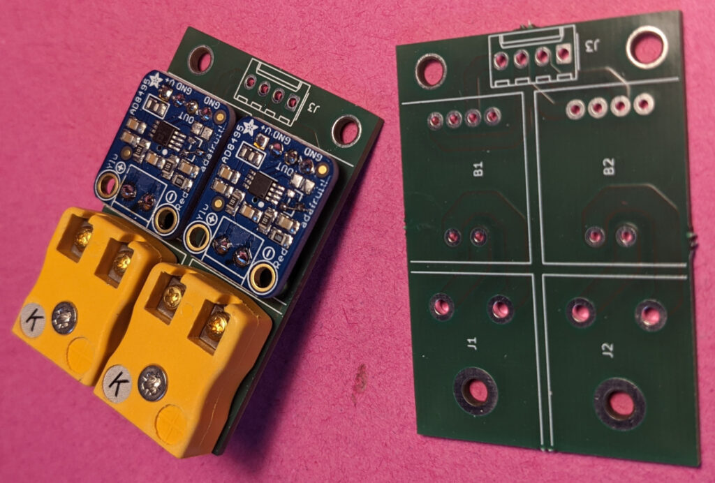
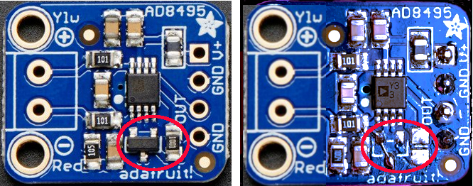
With a 5 volts power supply, the temperature range of the Adafruit board extends from -250°C to +750°C, which is not enough since the maximum temperature allowed for the Rotax 912 EGT is 880°C. The temperature range of the AD8495 circuit can extend from 0°C to 1000°C. A modification of the Adafruit board is therefore necessary. The goal is to remove the offset applied to the AD8495 REF pin via a TLVH431 shunt regulator and a 1k resistor. The purpose of this offset is to allow the measurement of negative temperatures, which is unnecessary here. The regulator and the resistor must be removed, and the REF pin must be grounded (Fig. 5 below). Given the small size of the surface-mounted components, a means of optical magnification is necessary, binocular loupes (mini x3.5) or stereo-microscope (max x10).
The voltage on the OUT pin is proportional to the temperature of the thermocouple. The AD8595 generates an output voltage of 5 mV/°C. With a 5 volts power supply, this output voltage ranges between 0 and 5 volts. With the above modification, the measured temperature of the Adafruit board ranges between 0 and 1000°C. The output voltage range should be reduced from 0-5V to 0-3.3V before connecting to an analog pin on the Teensy 4.1 board used in our EMS. The EGT input stage of the EMS can be seen in figure 6 below.
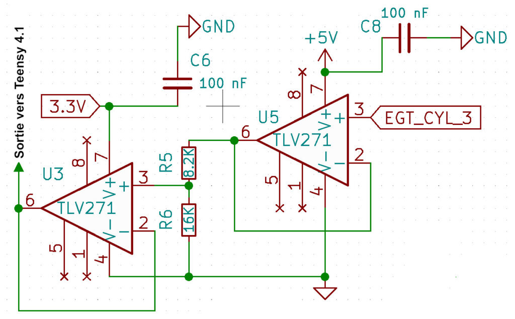
This input stage includes two TLV271 operational amplifiers (Op-Amp). The first one(U5), supplied with 5 volts (like the maximum output signal of the AD8495), is configured as a follower (unity gain non-inverting op amp circuit or voltage buffer). It copies exactly the input voltage (pin 3) on its output pin (pin 6). Its extremely high input impedance prevents from loading the output impedance of the AD8495. Its almost zero output impedance makes it possible to supply the voltage divider R5-R6 without any risk of voltage drop linked to the resistors. The values of R5 and R6 are chosen to convert 5 volts to 3.3 volts:
5 volts x R6/(R5+R6)=3.3 volts.
The second Op-Amp (U3) is supplied with 3.3 volts. It is also configured as a follower on the same principle. Its almost infinite input impedance prevents from loading the output of the R5-R6 voltage divider. Its almost zero output impedance is connected to an analog input pin of the microcontroller, protecting it from any risk of voltage greater than 3.3 volts.
The code that converts a voltage to a temperature in degrees C is as follows. It is an extract from our EMS software.
#define pinEGT3 A17
float EGT3;

void setup() {
 pinMode(pinEGT3, INPUT_DISABLE);
}

void loop() {
  // .......
 int digitalValue = analogRead(pinEGT3);
 EGT3 = (digitalValue *5/1023.0)/0.005;
  // ........
}
In our EMS, the output of the U3 Op-Amp is connected to the analog pin A17 of a Teensy 4.1. In the setup, we explicitly indicate that this pin is not intended to receive a digital signal. The instruction analogRead() on A17 results in a 10-bit value between 0 and 1023. In the following line, this value is first converted to a voltage between 0 and 5 volts (like the output of the AD8495), then this voltage is divided by 5 mV to obtain the temperature value. Remember that 5 mV on the output of AD8495 correspond to 1°C.
Hi Steve,
My apologies for taking so long to reply.
Thank you for your kind comments and thoughts on EGT signal noise.
New ideas are, of course, welcome.
If you start building, keep us updated on your progress!
Kind regards,
Benjamin
Just discovered this project and am binge-reading! Awesome stuff. Thought on signal noise for EGT probe… I have some experience in pro audio, and we solve signal interference using differential amplifiers (e.g., XLR cables). This is for AC signal, but the same can be done with DC using twisted pair, much like shipped CAT-6 network cable. The two parts of each pair are wound together so they experience virtually the same interference. Then a differential amplifier is used to only amplify the difference, leaving the interference out. Did a bit of digging and this is apparently done on thermocouples with long signal lines or noisy environments like this. TI has a couple basic circuits using one of their chips (LM94022).
Anyhow, awesome work! Can’t wait to start building some experimental avionics!
snoa544a
Hi Toufou,
Have you tried using shielded cables? Maybe you can improve the grounding as well. Ground loops often cause noise and instrument interference. Be sure that everything is grounded in only one place, at best on the engine. With the Adafruit AD8495 analog amplifier, using ground-insulated thermocouples might be deleterious. Are you sure that yours are not ground-insulated?
Hello,
I’m trying to do the same thing for a 2 stroke engine on a paramotor since 6 years…
I’m using the same adafruit board, it’s working like a charm…unless I start the motor, I have too much interferences with, I thing, the high-voltage of the spark plug ignition coil.
Have you an idea to reduce the noise ?
Thanks