(ESP32 EFIS-EMS: last updated by Benjamin on April 10, 2026)
ESP32 EFIS-EMS is a completely redesigned system that combines an EFIS and an EMS on a single 7-inch display. The previous system featured two screens, one for the EFIS and the other for the EMS, both powered by Teensy 4.1 boards. This new system stands out by introducing ESP32 microcontrollers. These microcontrollers, on the one hand, enable significant improvements to the graphical user interface and, on the other hand, enable wireless communication between specific components.
Readers are encouraged to refer to the “TFT-LCD display for DIY avionics” and “Microcontroller boards” pages, which have been revised accordingly. One of the main goals of this new system was to completely overhaul the user interface to give it a look more similar to that of professional instruments. Two other objectives were to minimize the overall system size and to improve the quality of connections to the many sensors.
A pre-prototype of this system has first undergone successful flight tests, as shown below. These tests aimed to validate several options and innovations, enabling evolution toward the current final architecture.
ESP32 EFIS-EMS Architecture
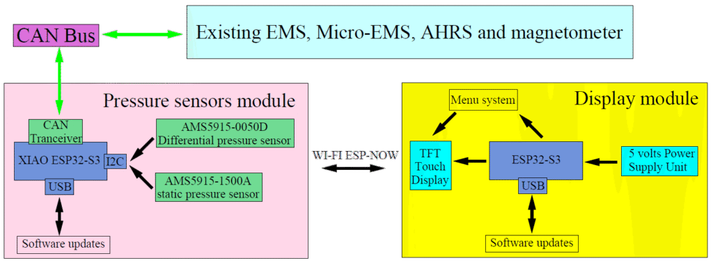
The ESP32 EFIS-EMS incorporates several existing elements that remain unchanged, namely the AHRS, the micro-EMS, and the remote magnetometer and external temperature and humidity sensor module, or RCM (Remote Compass Module). Two new modules are introduced: a display module and a remote data acquisition module, or RDAM. The RDAM should be considered the central data acquisition module. The AHRS, micro-EMS, and RCM are specialized data acquisition modules. All these modules communicate with each other via the CAN bus. Additionally, the RDAM and the display module communicate with each other over Wi-Fi. This architecture is illustrated in Figure 1.

This modular architecture aligns with the overall IMA (Integrated Modular Avionics) philosophy of the AvionicsDuino project. The modules each handle a specific function and communicate with one another via the CAN bus. The advantage of this modular architecture is the ease of maintaining and evolving the entire system.
ESP32 EFIS-EMS provisional prototype
To validate this new system and continue development, a temporary prototype was first flight-tested, as mentioned above.
The display module prototype
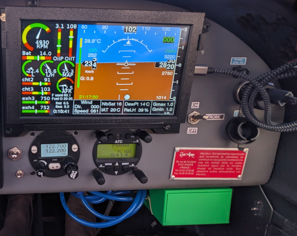
This prototype included a 7-inch commercial display module with IPS-quality performance and an 800 x 480 resolution. The graphics controller for this display is an ESP32-S3 system-on-a-chip (SoC) integrated into a PCB bonded to the back of the TFT panel. The entire graphical interface is therefore programmed on this ESP32.
This display features a capacitive touch layer, which enabled testing of a menu system without buttons or rotary encoders under real-world conditions. It was also desirable to test under direct sunlight a glossy, medium-brightness (400 cd/m²) display, which is representative of similar commercially available touchscreen displays. And also to test the ESP32’s wireless communication capabilities using Espressif’s ESP-NOW protocol, which operates over Wi-Fi. For these initial tests, the only electrical connection of this display module to the aircraft was its power supply. It was not connected to the CAN bus.
For these initial tests, no changes to the aircraft’s electrical circuits or the existing instruments on the panel were required. The display module, mounted in a 3D-printed ABS enclosure, was placed on a temporary support in front of the glove compartment. It was powered via its USB port, connected to a phone charger plugged into the aircraft’s cigarette lighter socket.
The temporary pressure sensor module
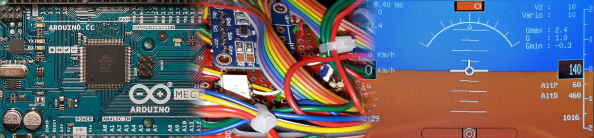
Therefore, a small additional module was specifically designed for these tests, also based on an ESP32-S3 chip, and foreshadowing the future RDAM. It was connected to the CAN bus and communicated with the display module via ESP-NOW, serving as an intermediary between the display module and the rest of the avionics.
This module included, in addition to a CAN bus transceiver, a barometric pressure sensor (AMS5915-1500A) connected to the static pressure circuit, and a differential sensor (AMS5915-0050D) connected to the static port and Pitot probe (the same pressure sensors as the current Teensy EFIS). The module received all engine data via the CAN bus from the existing Teensy EMS and micro-EMS, as well as other EFIS data from the AHRS and the remote magnetometer.
No changes to the software of the EFIS, EMS, micro-EMS, AHRS, or remote magnetometer were necessary for these tests, as all data processed by these instruments were already being sent to the CAN bus. This module was placed in a temporary 3D-printed enclosure, secured with Velcro under the instrument panel (Fig. 2).
For these tests, the system architecture was therefore as shown in Figure 3.
Therefore, this prototype was operating in parallel with the existing Teensy EMS and EFIS systems.
Provisional prototype flight test results
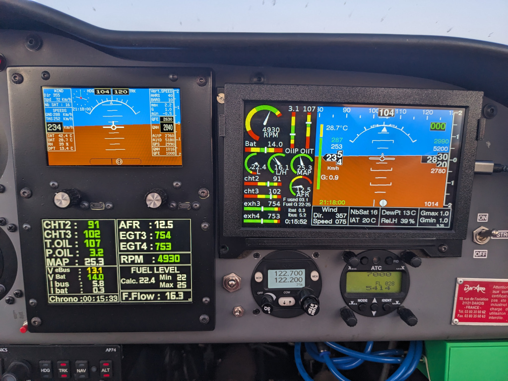
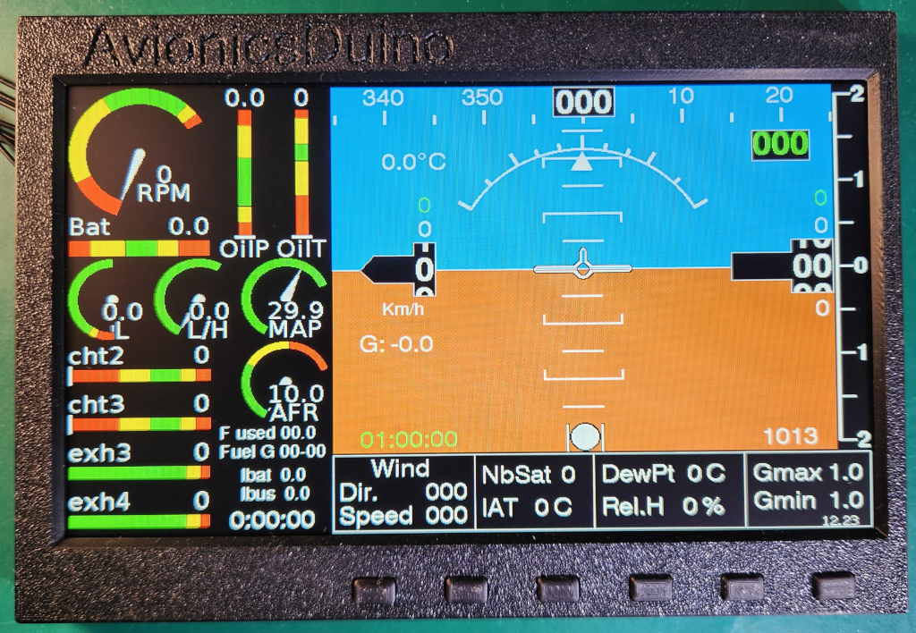
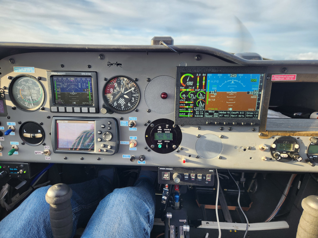
They validated the essential principles of this new system and identified areas for improvement. The photo in Figure 4 and the video below (Video 1) were taken during the first test flight. In the image, the ESP32 EFIS-EMS is on the right, with its single display, and the Teensy EFIS and EMS on the left. Below and to the right of the instrument panel, you can see the green temporary module.
Data comparison
The data displayed by both systems were identical, including those from the two sets of pressure sensors in the two EFIS. These EFIS pressure data had undergone extensive validation, partly by comparing them with the reference Dynon D10 EFIS installed on this aircraft (see the EFIS page) and partly through an experimental study of the pressure sensors used (see the EFIS pressure sensors page).
ESP-NOW and electromagnetic compatibility
The ESP-NOW communication between modules was faultless. No electromagnetic interference was observed between this prototype, housed in temporary non-shielded enclosures, and the aircraft radioelectric system. Despite the suboptimal PCB design of the temporary pressure sensor module.
Display quality and touchscreen ergonomics
This first flight was conducted under ideal conditions at sunset. The photo and video were taken with a low-angle, low-intensity light from the front. Of course, no reflections were noted on the matte displays of the Teensy EFIS and EMS. Very mild reflections on the glossy ESP32 EFIS-EMS display were tolerable.
However, during subsequent daytime flights, with the sun much higher in the sky and directly on the display, 400 cd/m² proved seriously insufficient. Additionally, this glossy touchscreen is prone to strong reflections, glare, and mirroring, unlike the matte non-touch displays.
Moreover, while it seemed satisfactory on the bench, using the touchscreen menu proved ergonomically poor and quite tedious in even mild turbulence, despite the precaution of programming large tactile buttons, as seen in Video 2.
New version of the display module
Regarding reflections on touchscreen displays, anti-reflective filters could have been considered, but they reduce brightness and sharpness. Therefore, they are not an ideal solution, especially on screens that are already insufficiently bright.
Since no 7-inch, matte, IPS, sunlight-readable ESP32 non-touch screen was available on the market, it was necessary to make one. It is based on a custom printed circuit board using an ESP32-S3-WROOM 1 N16R8 SoC and a Newhaven NHD-7.0-800480AF-ASXP TFT panel. This panel is matte, IPS, non-touch, and has a brightness of 1000 cd/m².
For interaction with menus and the graphical user interface, the touchscreen was definitively abandoned in favor of a row of six push buttons located below the screen.
Results
The overall appearance is shown in Figure 5, which depicts the display module in its 3D-printed ABS enclosure.
Bench tests were very satisfactory. The matte 1000 cd/m² screen remains perfectly readable under direct sunlight, with no reflections or mirroring, and the keyboard works flawlessly (video 3).
The design of this display module is now stable; no further changes are planned. Without making any changes, it can use either an ESP32-S3-WROOM 1 or an ESP32-S3-WROOM 1u module; the latter has a U.FL connector for a remote Wi-Fi antenna rather than an antenna embedded on the SoC’s PCB. This could be useful to improve the quality of ESP-NOW communication with the RDAM. For example, if the two modules are placed on opposite sides of an aluminium instrument panel, that could act as an RF screen. The display module is also equipped with a CAN transceiver, in case the CAN bus is preferred to ESP-NOW. With some software adaptation, users can therefore make their own choice.
Display Module download section
KiCAD V8 files (Note: This file is OK; the minor silkscreen error from the previous version has been fixed.)
Gerber and drill files (Same note as above)
AvionicsDuino ESP32 EFIS-EMS: Download source code on GitHub
For the display module, in the Arduino IDE, select the ESP32S3 Dev Module board. Then Flash Size: “16MB (128 Mb”, Partition Sheme: “Huge APP (3MB No OTA/1MB SPIFFS)”, PSRAM: “OPI PSRAM”.
The Remote Data Acquisition Module
There were several choices to be made: should separate PCBs be used for the EFIS and EMS, as in the current Teensy AvionicsDuino system, or should they be combined on a single PCB? And on the other hand, which microcontroller to use: Teensy 4.x or ESP32?
The PCB
To maximize space utilization, a single 4-layer PCB was selected to increase component density and further improve compatibility and immunity against electromagnetic interference.
The microcontroller
Regarding the microcontroller choice, the ESP32-S3 was selected to leverage Wi-Fi ESP-NOW connectivity with the display module. The Seeed Studio XIAO ESP32-S3 board is ideal for its compact form factor. However, as a consequence of this choice, the well-known issue with the ESP32’s poor analog-to-digital converter (ADC) has arisen.
ESP32 ADC issues
Like many users, we observed nonlinearity in the only available ADC (the second is reserved for the system). By following Espressif’s calibration procedure, the linearity could be improved. But there is a second issue with this ADC: it is noisy (especially compared to the ADCs on Teensy 4.x boards), especially when Wi-Fi is active.
Therefore, it was decided to use two external I2C ADCs (ADS7828), one for ratiometric sensors and the other for non-ratiometric sensors.
A first prototype and then the definitive RDAM have been assembled and tested. Numerous preliminary bench tests on small sub-assemblies gave cause for optimism. However, it was necessary to demonstrate that a single ESP32-S3 could simultaneously manage Wi-Fi, the CAN bus, and six slave devices on the I2C bus (two external ADC and four pressure sensors) while maintaining a sufficient sampling rate. Knowing the other shortcomings of the ESP32.
Other ESP32 potential issues
The I2C bus
A concern could specifically have come from the I2C bus. Even when strictly following Espressif’s procedures for I2C bus and slave device initialization, oscilloscope and logic analyzer readings show non-reducible latencies of 50-70 µs between I2C transactions, decreasing bus bandwidth. This could potentially impair the sampling rate and, consequently, the quality of digital data filtering. Such latencies were not observed with Teensy boards.
The noise issue
A second cause for concern was noise. External ADC tests on breadboards, using jumper wires and Dupont connectors, without a ground plane, raised serious concerns about what might come next. In similar experimental conditions, Teensy boards, with their own ADC, proved much less noisy.
The first prototype of the 4-layer PCB, with two ground planes, demonstrated that the design was sound. Despite the aforementioned latencies, the sampling rate of the 6 slave devices on the I2C bus is excellent (300 Hz), while also ensuring the necessary communication over the CAN bus and Wi-Fi for ESP-NOW.
The ground planes and the strict analog-digital separation on the PCB significantly reduced noise compared to the initial breadboard tests. Digital filtering virtually eliminates residual noise.
The definitive RDAM
Some minor changes to the first prototype were necessary due to design errors (specifically, incorrect footprints for some components and the omission of ground points among the PCB test points). The final RDAM PCB is now ready.
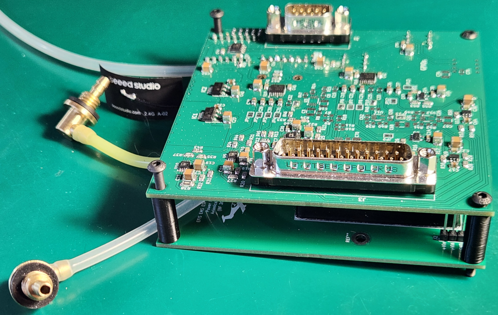
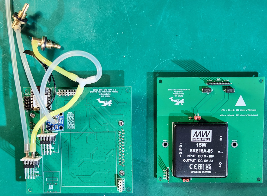
Actually, there are two PCBs sandwiched together (Fig. 6). The top four-layer PCB houses all the components and SUB-D connectors on its top layer, and all the pressure sensors on its bottom layer. The two-layer bottom PCB is the power supply module, providing 5 V from the 14 V aircraft electrical system (Fig. 7). The two PCBs are connected via mezzanine connectors. Due to space constraints, the power supply module developed for the Teensy EFIS was not reused for the ESP32 EFIS-EMS, in favor of a commercially available power supply module.
The Modular Nature of the RDAM
This is an important characteristic of the RDAM. The components for each function are grouped together. Thus, if not all functions are needed in a particular installation, the relevant components simply need not be soldered onto the PCB.
The available inputs of the AvionicsDuino RDAM
- 2 for cylinder head temperature
- 4 for exhaust gas temperature
- 1 for oil temperature
- 1 for coolant temperature
- 2 for oil pressure (1 resistive, 1 Keller)
- 2 for shunt-based current measurement (1 unidirectional, 1 bidirectional)
- 1 for an O2 sensor controller (air-to-fuel ratio measurement, AFR)
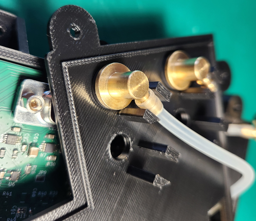
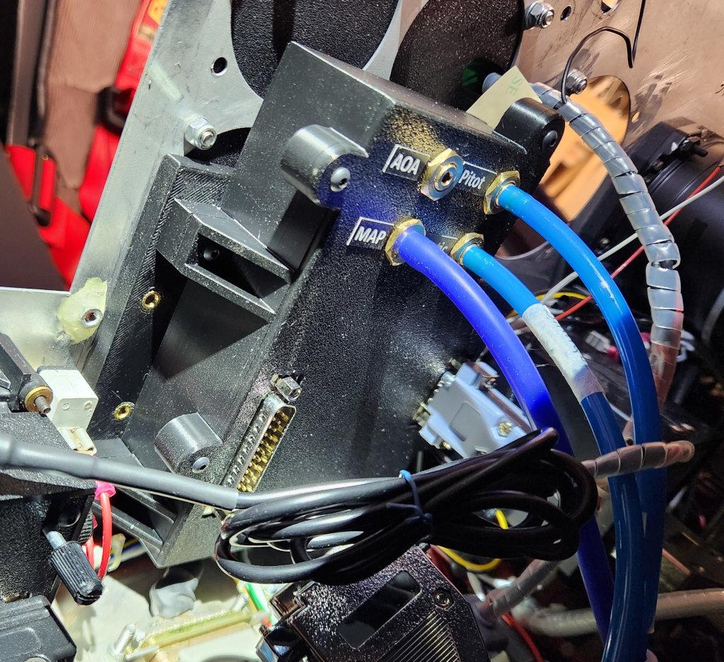
- 4 pressure sensors (Static, Pitot, AOA, Intake Manifold Pressure)
The inputs used in the above flight tested RDAM
- 2 cylinder head temperature, CHT2 and CHT3
- 2 exhaust gas temperature, EGT3 and EGT4
- 1 oil temperature
- 1 VDO resistive oil pressure sensor
- 2 shunt-based current measurement
- 1 AFR
- 3 pressure sensors (Static, Pitot, Intake Manifold Pressure)
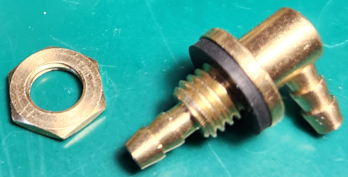
The engine is a carbureted 80 CV Rotax 912 UL equipped with a variable-pitch propeller and a homemade back-suction-type mixture control system.
Therefore, many component pads remain free, as shown in Figure 6. A simple way to keep unused pads free of solder for possible future use is to mask the stencil with adhesive aluminum tape before applying the solder paste (Fig. 13).
Readers who would like more technical information on the RDAM are invited to read the document “The RDAM PCB: Why and How?”, available for download below.
Remote Data Acquisition Module download section
Main PCB Gerber and drill files
Power PCB Gerber and drill files
AvionicsDuino ESP32 EFIS-EMS: Download source code on GitHub
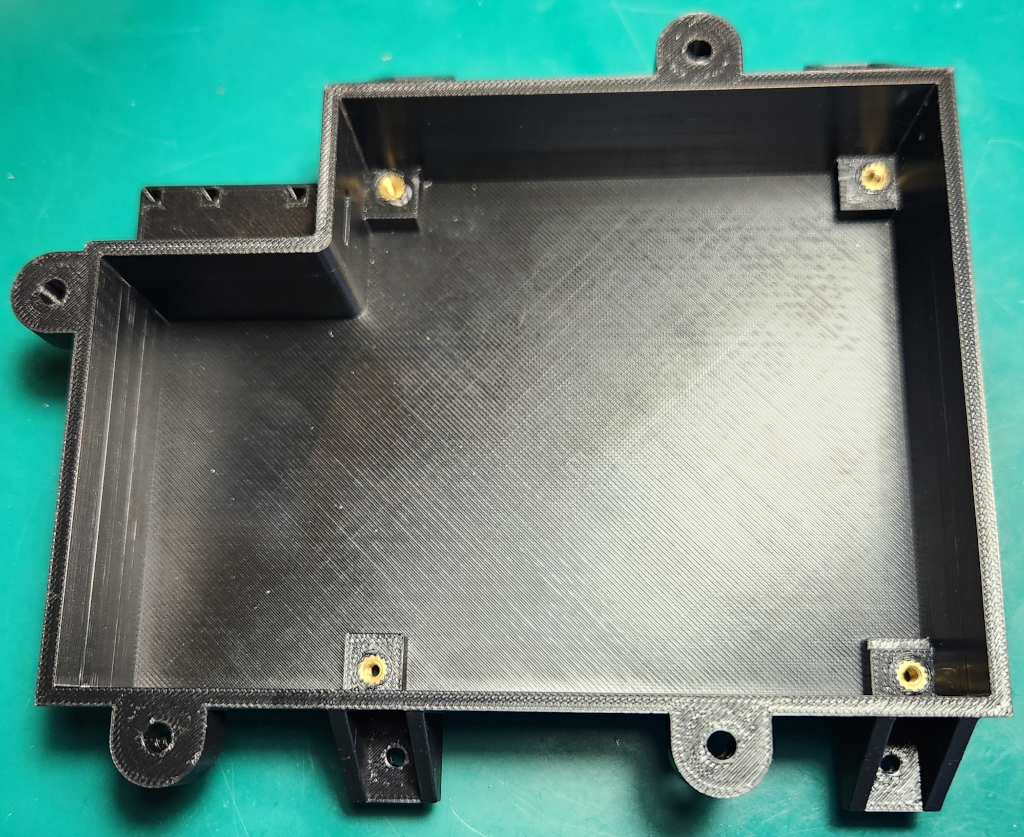
The STEP files for the RDAM enclosure are provided here primarily for illustrative purposes. The installation in the aircraft used for testing the ESP32 EFIS-EMS is specifically adapted to that aircraft, particularly regarding the RDAM mounting plate on the instrument panel. This plate is fixed to the front side of the panel, using the screw holes left by previous analog instruments, while the display module is fixed to the rear, facing the pilot, using other existing screw holes. The arrangement of these components could be very different in another aircraft.
For the RDAM, in the Arduino IDE, select the XIAO_ESP32S3 board. Then Flash Size: “8MB (64 Mb”, Partition Sheme: “Maximum APP (7.9MB APP No OTA/No FS)”, PSRAM: “OPI PSRAM”.
Flight tests
The first test flights, as expected, revealed a few bugs and software imperfections (insufficient filtering of certain values, errors in calculating currents and G-gorces, QNH setting error, magnetic heading display bug, and circular dial needle display issues on the EMS).
However, the hardware worked immediately as expected. The ESP-NOW communication between the display module and the RDAM functions perfectly. No electromagnetic interference with the aircraft’s electric and radio installation was observed.
The various graphical or textual displayed items are perfectly readable and smooth despite the modest screen refresh rate (between 11 and 12 Hz). The brightness and colors are exceptional, far better than those of the Dynon EFIS D10A, as seen in the videos below (videos 4 and 5). The screen remains readable even in direct sunlight, without glare. The 6-key mini-keyboard makes navigating menus very easy, even in turbulent conditions.
All bugs and display issues were easily fixed. The latest versions of the RDAM and display module programs are available on GitHub.
User guide
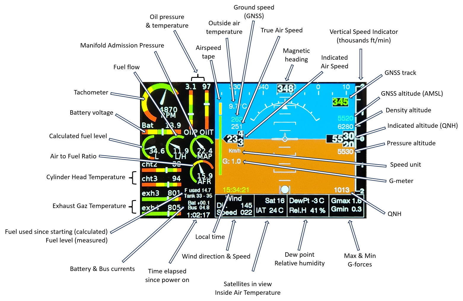
Figure 11 presents all the elements displayed on the screen.
The displayed magnetic heading is not corrected for local declination. However, this must be entered under one of the options in the SETUP menu; it is used to calculate wind direction and speed.
Pressing any key opens the menu at the bottom of the screen, below the artificial horizon. Most of the options are very straightforward and do not require detailed explanations.
The PRESS. CORR. option in the SETUP menu should be used on the ground, at an airfield with the lowest possible AMSL altitude. It allows correction of any indicated altitude error due to a slight offset (zero error) in the barometric sensor. You should start by setting the altimeter to the local QNH with the menu FLIGHT -> QNH. If the indicated altitude matches that of the airfield, no correction is needed. If not, adjust PRESS. CORR. until the indicated altitude is correct. The unit of PRESS. CORR. is the tenth of a Pascal.
Short-term planned developments
A new menu option will be added to allow correction of a possible altitude error proportional to altitude (span error).
This will be useful on the above-tested EFIS-EMS. On the ground, at the same QNH, the three aircraft altimeters indicate the same altitude. But during climb, a small offset, proportional to altitude, gradually increases linearly. At 5,000 ft, the ESP32 EFIS-EMS indicates an altitude approximately 40 to 60 feet higher than the Dynon and Falcon altimeters, which have been previously verified.
The potential error is specific to each sensor used and can vary from one sensor to another. The Teensy EFIS software (which uses the same pressure sensors) includes such a correction in its code; it is not adjustable in the menus.
A new calibration procedure for the remote magnetometer is currently being studied, based on mag data recorded during flight. At present, the magnetic heading is not always sufficiently accurate because the magnetometer was calibrated before being mounted inside a winglet, which is suboptimal.
Ok, Thanks for the report…
Hello Daniel,
Amsys sells its sensors directly, without going through the usual electronics wholesalers.
Yous can send an email to info@amsys-sensor.com, requesting a proforma invoice including Amsys bank details for 1 AMS 5915-1500-A and 1 AMS 5915-0050-D with 2 distinct I2c addresses (very important).
Benjamin
Good morning Benjamin… I have the complete BOM except for the AMS5915-1500A and AMS5915-0050D pressure sensors, which I can’t find anywhere. I also had to change the brand of some other components due to lack of stock, but that’s not a problem.
Could you provide me with a link or website where I can buy the two sensors?
Thanks
Hello Marcos,
You are absolutely right. There was an error on the PCB’s silkscreen layer; the R4 and R5 markings were swapped. I’m sorry for the error. I noted it for a few weeks next to the download link, but you may have downloaded the files before I pointed it out. I corrected the KiCad and Gerber files a few days ago.
I didn’t make the mistake myself when soldering my components, as I always use the xxx_BOM.html file for component placement, which is very convenient. In fact, that’s how I discovered the error.
I am especially sorry because, although I knew about the error, I didn’t even consider it the cause of your difficulties… My sincerest apologies.
Thank you for the photos, and well done!
Benjamin
Hello Benjamin,
Finally the last items from Mouser arrived and the screen is complete. As I told you before, I´ve some problems to start the USB bridge when plugged on the computer. Correct me if I´m wrong but I solve the problem changing R4 by R5. I think that there is an error on the PCB masking layer and R4 and R5 should be swapped.
I also compiled and install the proper software for the final circuit and it´s working as expected.
Thanks so much for your time and Best Regards
Hi Marcos,
Thanks you for your comment.
Congratulations on the 3D printing. There aren’t many mechanical stresses on these enclosures, so PLA is probably fine.
I’ve recently started working with a Bambu Lab P1S enclosed printer, which makes it easy to print in ABS.
I’ve always made aluminum enclosures for electronics, and my concern with 3D printing was about electromagnetic interference. So far, I haven’t encountered any problems. The electrical circuit in my aircraft was built according to best practices, notably with a single ground point, so it’s less susceptible to interference. Furthermore, the various PCBs were designed to minimize the risk of interference. Finally, modern VHF radios and transponders are probably much more resistant to interference than older models.
So 3D printing seems OK! I hope the future confirms this positive impression.
Benjamin
Hi Daniel,
Thank you for your kind comment.
Yes, the project has progressed significantly. I still have a few checks to perform in flight, but the initial flight tests are very satisfactory.
I can confirm that with the final version of the ESP32 EFIS-EMS, the previous Teensy EFIS and EMS are not required. The EFIS-EMS itself comprises two modules: the display module and the RDAM. However, it requires three other sensor modules: the AHRS, the RCM (Remote Compass Module, which also integrates a relative humidity sensor and a temperature sensor), and the micro-EMS (fuel management, tachometer, voltage monitoring).
Benjamin
Hello Benjamin, nice to hear that the RDAC is almost ready ¡¡¡¡¡¡ Congratulations for your impeccable work and time spent on these project.
These days I wipe de dust of my 3D printer and putting into operation again….. After repairing the struder motor and driver I printed out the first prototypes both in ABS (rough finish…) and in PLA with better results. Here some pics of the progress.
With Best Regards, Marcos
My sincerest congratulations on the progress, the publication, and the results…
This project is more than ready.
For my part, I’ll start by ordering the components and boards for the AHRS, magnetometer, and display module. The EMS module, from what I’ve read, might not be necessary; could you confirm that?
On another note, the minimum order for PCBs is 5, so if anyone I know is interested in any, I’d be happy to send them.
Thanks for all
Hi Marcos,
Great, it’s off to a good start!
I’ve already assembled two screen PCBs; neither worked perfectly on the first try. For the first one, no COM port was recognized on the PC when I plugged in the USB cable, so I couldn’t upload the program. Examining it under a 10x stereo microscope revealed that the CP2102N chip was very slightly lifted by excess solder after hot-plate reflow; there was a poor solder joint on one of the pins, invisible to the naked eye. For the second PCB, I preferred to solder the CP2102N by hand. But in this case, the SN74HC14DBR chip was faulty, so I had to replace it.
It’s not the absence of ESD diodes D3 and D4 that’s interfering with the USB-UART bridge. I removed them from my first PCB before discovering the bad solder joint on a pin of the CP2102, and I didn’t put them back afterward; everything worked fine after correcting the bad solder joint. Perhaps all the solder joints should be carefully rechecked with good optical magnification.
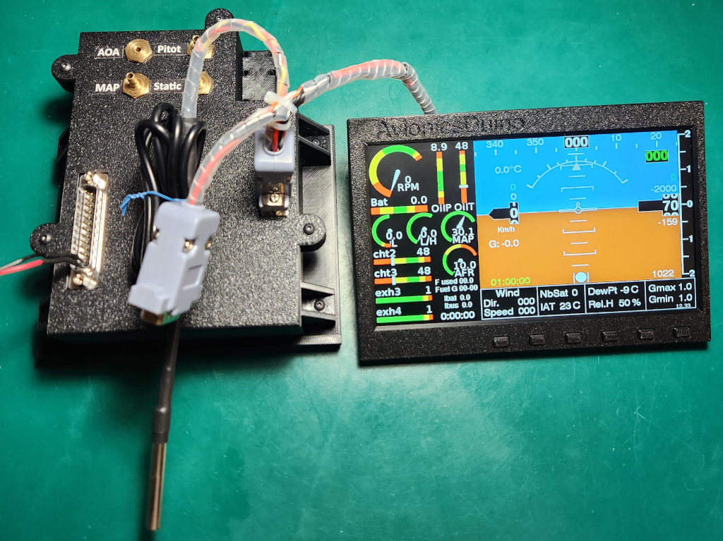
Regarding the EMS, I suggest you wait a bit, as the ESP32 EFIS-EMS RDAM will be flight-tested in the coming days (photo below). All bench tests are satisfactory. I prefer to wait until I have completed successful flight tests before publishing the schematic and BOM of this RDAM on the website.
Benjamin
Hello Benjamin, Yesterday I´ve tested the PCB again and found a bad pin connection on J1 (40 pinout display connector…). After solve it the display is working fine ¡¡¡¡ I´m still have some problems to start the USB bridge but suppose to be the absence of D3 and D4 (ESD diodes) that I´m still waiting to receive from Mouser. When I connect the USB it takes a while until COM PORT on computer is detected or sometimes I need to “touch” any of the resistors around the USB bridge to work. After detected it works fine till next power it up…..
I look forward the data logger completion and in the meanwhile I´m building the AHRS, Compass and EMS circuits. Thanks a lot for your great work¡¡¡¡
Hello Benjamin, thanks a lot for your imputs on that.
I have a lab power supply with full control of both current and voltaje so I power the led wires with average 80 mA so I get enought light on the screen. But right now I’m working outside home for a week or so and no choice to test. I’ll keep you updated one’s more test are done.
With Best Regards, Marcos
Hi Marcos,
If you can upload programs and get messages on the serial monitor, that’s already excellent. This indicates that the entire USB-UART section is functioning properly. And the CP2102N is by far the most difficult component to solder.
If the screen displays nothing, it might be because the current supplied to the backlight LED array is insufficient. Are you using a lab power supply that actually allows for precise control of the current and voltage?
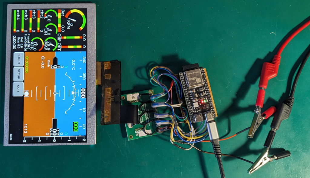
I dug out one of the very first preliminary test prototypes I made, the one I used to test the connections between the ESP32 and the Newhaven TFT panel. See the photo below.
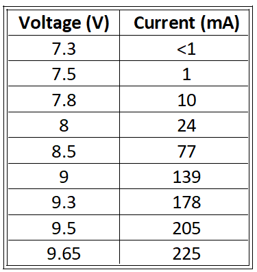
The screen’s LED array is powered by a DC lab power supply; those are the black and red wires in the photo, with the alligator clips. The ESP32 board is an Espressif ESP32S3 N16R8, powered by its USB connector. The board-to-screen wiring is the same as in the ESP32 EFIS-EMS display module. The power supply has been set to deliver no more than 225 mA, the maximum current specified in the display’s datasheet. The table below shows the currents obtained at various voltages, with a Newhaven NHD-7.0-800480AF-ASXP panel. Caution, for other panels, this might be very different!
225 mA are observed at 9.65 volts. Below 7.3 V, no current flows, this is below the forward threshold voltage of the LED array. At 7.3 V, the current is below 1 mA, but in dim light a faint image can be seen on the screen. At 7.5 volts, the current is 1 mA, and the image becomes clearly visible in low ambient light. From 7.8 V/10 mA, the image on the screen is clearly visible in normal indoor lighting.
At 9 volts (139 mA), the screen backlight is clearly visible, even if the ESP32 board is not powered. The two are independent; there is no synchronization or interconnection between the ESP32 and the backlight. Therefore, even without an image, you can check if the backlight is working. By applying 9 volts between pins 1 and 2 of the FFC 40 ribbon cable, you should see the screen light up slightly, even if all the other wires on the cable are disconnected. You should also observe a current of approximately 140 mA.
If the backlight is working correctly, but nothing is displayed on the screen, the second thing to check is that there is a voltage of 3.3 volts on pin 4 of the FFC ribbon cable. If that’s the case and nothing is displayed, then there’s probably a faulty connection between the ESP32S3 module and the FFC connector. Of course, you also need to make sure the ribbon cable is connected correctly, but that was the case in the photo you posted on January 30th.
Keep us updated.
Best regards,
Benjamin
Hi again Benjamin, sorry for late response but I been working outside home these dates……
I´m still pending to receive some components from Mouser as there are no stock (2 ESD diodes and the back light controller…). I´ve compiled your test software for the screen with successfull and load it but nothing happend on the screen. For back light I connect temporally an regulated power supply feeding 100 mAmps for it. I´m not sure if the backlight signal must be sincronised with control bus signals as to “start” the display. The ESp-32 is working as I can read messages thru USB COM Port.
With Best Regards, Marcos
Hi Jon,
Thank you for your kind comments.
For shipments to the UK and, more generally, outside Europe, customs formalities would be cumbersome, complex, and time-consuming for me as I’m not a professional seller, and would likely be quite expensive for you compared to the price of the PCBs. Therefore, I think it’s probably simpler and cheaper for you to order the PCBs either from a UK manufacturer (if you know one), from Germany (there is a good and cheap one), or from China.
The KiCad and Gerber files for the display module are already available for download; those for the RDAM will now be available very soon.
Benjamin
Hi Benjamin.
Do yo have any unpopulated pcb’s for sale for the ESP32 EFIS-EMS.
I would rather buy from you as the originator of this brilliant project than have them made here in the UK.
Rgds
Jon Parnaby
Hi Benjamin.
I read one of the comments about you having some unpopulated pcb’s for the updated efis.
I am building an aircraft at the moment and like the idea of DIY efis.
Do you still have the pcb’s and would you be willing to sell me one. I am in the UK
Hi Chris,
Ah! I misunderstood. I do have some unpopulated PCBs, and if you were in Europe, it would have been easy to ship a set, but I believe you’re in the USA. As you know, the new customs regulations now make it virtually impossible for an individual to send packages to the USA. You’ll be much quicker and far cheaper ordering PCBs from the USA, for example, from OSH Park. The KiCad and Gerber files for the ESP32 EFIS-EMS display module are available for download right now, and those for the remote data acquisition module will be available very soon.
Benjamin
Benjamin, completely understand. I was hopefully looking for unpopulated PCB’s, I can solder all the components. Maybe start a group buy and get some good pricing???
CR
Hi Chris,
Thank you for your kind comments.
Regarding the purchase of ready-made boards, please refer to my reply to Steven on this page dated December 19, 2025.
The avionicsduino website is DIY-oriented, run by volunteers, and non-commercial.
Many PCB manufacturers offer component assembly as an option. However, this is often quite expensive, so it’s better to do the work yourself. If you’re not comfortable soldering SMD, there are many tutorials online and on YouTube, so we decided not to create another one on avionicsduino.com.
Benjamin
Thank you for all your work on this!!! Will you have PCB’s available?
Benjamin, incredible work!!! Are any of these boards for sale, or do they have to fabricated? I have no problems with soldering, but would much rather have them made by you if possible.
Hi Cédric,
STM32 microcontrollers do indeed have a more professional reputation than ESP32s. However, ESP32s are more economical and accessible to hobbyists. Until recently, we used only NXP iMXRT1062s on Teensy boards, but the emergence of low-cost ESP32-based display controllers has prompted us to reconsider this choice. There are also STM32 Embedded Displays, but they are significantly more expensive.
So far, we haven’t had any ESP32s fail. “Pourvu que ça dure !”
Your contribution to the project would be greatly appreciated!
Best regards,
Benjamin
Hi Marcos,
Thank you very much for your kind comments. Congratulations on the four planes already built, and on the fifth, the magnificent ASSO X JEWEL little fighter!
As an electronics engineer, assembling the ESP32 display must not have been troublesome. I hope it’ll work as expected. I indeed did notice that the backlight controller isn’t soldered to the PCB yet.
Feel free to leave further comments if you have any questions or concerns. I would also be very happy to receive any suggestions.
Best regards,
Benjamin
Hello Henrique,
Many thanks for your kind comment.
My apologies for the late reply. The site has been malfunctioning quite a bit for the past few weeks, perhaps following a plugin update. I was no longer receiving notifications when comments were posted (hence the delay), and the email function stopped working altogether. And to top it all off, yesterday the site crashed completely; nothing worked. Fortunately, with the help of my hosting provider, I was able to restore normal operation, and there was no data loss. Phew!
We are, of course, always happy to discuss your projects. Feel free to ask any questions you may have in the website comments.
Congratulations on building your experimental aircraft.
Benjamin
Bonjour Stéphane,
Toutes mes excuses pour cette réponse tardive. Le site a pas mal dysfonctionné depuis quelques semaines, peut-être à la suite de la mise à jour d’un plugin. Je ne recevais plus de notification lorsqu’un commentaire était déposé (d’où mon retard), la messagerie mail ne fonctionnait plus du tout. Et en plus, hier, le site s’est planté complètement, plus rien ne fonctionnait. Heureusement, avec l’aide de mon hébergeur, j’ai pu rétablir le fonctionnement normal et il n’y a eu aucune perte de données. Ouf !
Donc avec retard, tous mes vœux également !
Je partage ton avis sur le bus CAN : pour l’EFIS-EMS ESP32, les utilisateurs auront le choix entre Wi-Fi/ESPNOW ou CAN bus.
Le projet avance bien, le RDAM est assemblé (photo ci-dessous), il fonctionne parfaitement au banc, il ne reste plus qu’à lui faire un beau boîtier et à le monter dans l’avion. Tout cela prend du temps, et je mène d’autres projets de front, comme un module Bluetooth BLE convertisseur RS232 pour envoyer les fréquences radio de Skydemon vers ma VHF TRIG. Et je participe à la mise au point d’un servomoteur pour le projet de pilote automatique géré par Gabriel.
Benjamin
RDAM : le PCB du dessus reçoit tous les composants et les connecteurs SUB-D sur sa face supérieure, et tous les capteurs de pression sur sa face inférieure. Le PCB du dessous est le module d’alimentation pour fournir une tension de 5 volts à partir du réseau électrique de bord de l’avion (12-14 volts)
Dear Benjamin,
Firts of all Thanks so much for sharing these project with all of us and dedicated so many time an effort.
I´m an amateur builder from the North of Spain, I´ve already built 4 planes of aluminium and wood. The last one is an RV-4 that I´m flight testing right now. At the same time I´m building an ASSO X JEWEL. I followed your web and improvements for some years now and finally I´m decided to start your project. I´m an electronics engineer so I ordered the PCB´s and components and asemble the 7″ EFIS&EMS with ESP-32 display. Also ordering the AHRS and Remote compass items. Right now I´m trying to complete as awaiting from MOUSER some diodes and display backlight controller. Congratulations for your job ¡¡¡¡¡¡ Best Regards, Marcos
Really nice.
I was searching for components to make my own EFIS and sensors and found the project.
I was more inclined to STM32 species because of the capabilities and proven durability.
I had some esp32 fail on industrial projects.
I will take a deeper look at your ecosystem and will contribute if I can.
Bonjour Benjamin.
Mes meilleurs vœux a toi, aux tiens, ainsi qu’a la communauté de ce site.
Tu évoques sur la version anglaise cette solution :
une Teensy 4.0, à peine plus grande, sans autre modification. On renoncerait alors au Wi-Fi au profit du bus CAN, sans véritable inconvénient. La solution Teensy 4.x est très robuste et éprouvée. Le surcoût, d’à peine plus de 10 € par rapport à la carte XIAO, est minime.
Je trouve le bus CAN comme étant une très bonne solution et permet d’étendre a d’autre accessoire ne disposant pas de wifi
Hello, congratulations on your work. My name is Henrique and I live in Brazil. I’m building an experimental aircraft in an advanced stage and I’m passionate about computer science. I’m not a programmer; I’m a hobbyist. I already have some experience with Arduino. I understand that the ESP32 EFIS EMS project is the most recent development. I have an ESP32 here for my experiments and I really enjoyed working with this powerful board. I read some articles on the website and would like to discuss the project further. Thank you.
Hello Steven,
Congratulations on the CP328, it’s a nice aircraft!
The avionicsDuino website was designed with a DIY spirit in mind, and at present, it would not be easy to take orders for a near-ready-to-use system. But if you can solder SMDs yourself, sending blank PCBs would be very simple. For populated ones, it is quite another story. However, things could change if there is demand. That being said, it is possible to order assembled PCBs from PCB manufacturers, of course at a significant additional cost, especially for a single PCB. But if several people were interested, it would be much more cost-effective.
Soldering many small SMDs onto a PCB can indeed seem daunting, but with an optical magnification, a 50€ hot plate, and a little care, it’s far from being insurmountable. A page on the site dedicated to soldering SMDs was planned, but there are so many SMD soldering tutorials online…
We’ll have the opportunity to talk about this again later, once the final version of the ESP32 EFIS-EMS is successfully flight-tested. I hope in the very first months of 2026.
Benjamin
I am interested in your project. I am currently building a CP328 Super Emeraude. Once you have your project ready for release will you take orders for the circuit boards needed for this project?