(TFT-LCD display for DIY avionics: last updated by Benjamin on March 25, 2026)
The selection of a TFT-LCD display for DIY avionics projects depends on many factors. Type of display, connection interface, library availability and quality, and brightness must be considered. The size and resolution will depend on the software application and the space available on the instrument panel. For an EFIS or EMS, to ensure excellent readability in all circumstances on the instrument panel, a size of 4.3 to 5 inches, a resolution of 480 × 272 pixels, and a brightness of 500 cd/m² are the minimum requirements. IPS technology offers valuable, wide viewing angles.
Touch screen or not? It is a matter of personal choice: during turbulence, selecting a small screen area or menu option may be difficult on a 5-inch (or smaller) display. Other control systems must be considered, such as push buttons, rotary encoders, or joysticks, which are often more precise than a capacitive touch screen. The latter also has the disadvantage of being glossy, whereas a non-touch, anti-glare, matte display is much more readable under direct sunlight.
Once the microcontroller/microprocessor (MCU/MPU) of the project has been selected, the interface between the MCU/MPU and the display is the primary technical specification to consider. Of course, it depends on the display type and the MCU/MPU type. There are several display interfaces, including HDMI, Serial, and RGB-parallel, to name the most commonly used. Once a display type and an interface are selected, all the above criteria must be considered.
How do display systems work?
We do not intend to explain the technology of LCD or TFT panels here, but rather how they interface with our MCUs. In the simple embedded systems we are interested in, there are four components: the TFT-LCD panel, the display graphic controller, the memory frame buffer, and the MCU/MPU.
The TFT-LCD panel
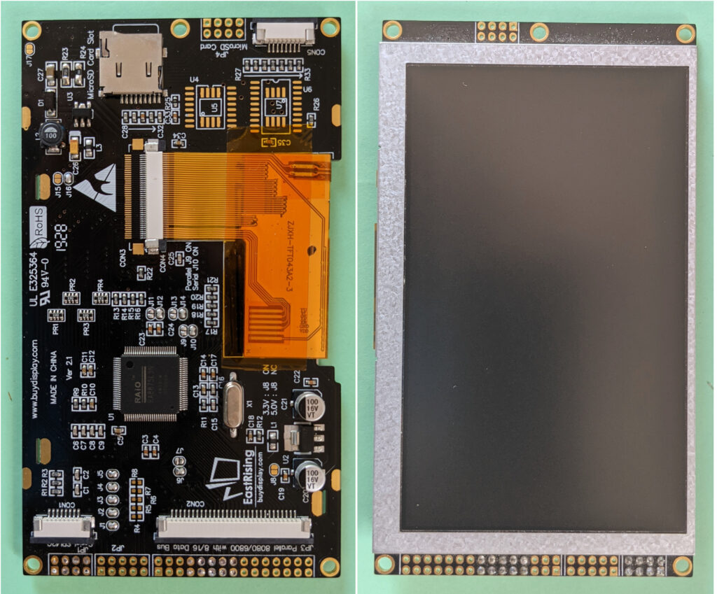
It is sometimes called display glass. Its role is to display images. In very simple terms, this panel consists of pixels. It receives electrical signals that, after proper processing, can individually turn the pixels on or off and determine their color and brightness. Figure 1 shows a typical TFT panel.
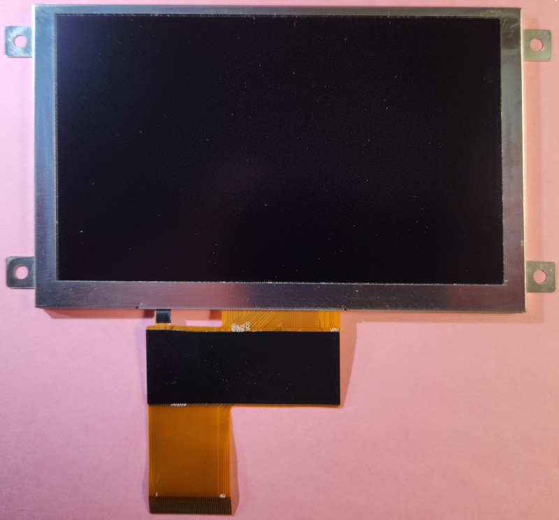
There are a limited number of signal lines (typically 40) entering the panel, and tens or hundreds of thousands of pixels need to be driven, depending on the panel’s size and resolution. TFT panels thus always include an IC driver chip that receives digital image data from the ribbon FFC cable and delivers analog voltages with exact timing to control each red, green, and blue pixel on the display individually. For example, the ST7277 from Sitronix is intended to drive 800×480 TFT panels; there are many others.
The display graphic controller
Its function is to read the memory frame buffer in a continuous loop and stream pixel data, along with synchronization and clock signals via the FFC to the display panel driver IC.
The frame buffer
It is a memory area that stores each pixel’s color information in real time. For example, if the panel supports 16-bit color depth (RGB 565, see below), then 2 bytes of frame buffer memory are required per pixel. If the panel resolution is 800 x 480 pixels, the minimum frame buffer memory requirement is 800 x 480 x 2 = 768 kilobytes.
The MCU/MPU
Its function is to compute the images to be displayed and feed the frame buffer accordingly with the proper data. It does not need to update the entire frame buffer at every frame. It only has to update in the memory what has changed from the previous frame.
Display types
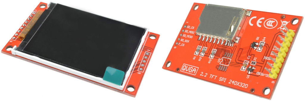
The four components mentioned above can be organized in different ways. Small displays with low resolution tend to have a built-in frame buffer and controller. For example, the ILITEK ILI9340 Driver unit is a 240×320 RGB 262K color TFT LCD Single Chip Driver that supports 16- or 18-bit color depths. It includes an IC driver, a graphic controller, and a frame buffer. This chip provides an SPI interface. Many small displays use this chip (Fig. 2)
Larger displays like the one in Figure 1 can be handled either by a basic microcontroller via a SPI interface and a specialized board including a frame buffer and a graphic controller (a good example is the RA8875, see below), or by a more powerful microcontroller including a frame buffer and a graphic controller (see below the ESP32 displays).
HDMI interface
Single-board computers (SBC)
Microcontroller boards never embed a real HDMI-type display connector. But SBCs, such as the Raspberry Pi under Linux or the LattePanda under Windows, have such an interface.
But computers, particularly their operating systems, are hardly compatible with power loss; they must be powered off cleanly. Embedded systems need to be designed so that any unexpected power loss (such as switching off the master switch on an aircraft) will not cause corruption in the operating system or data loss from the application software running on the device.
To be operated safely in an embedded application, a single-board computer requires measures to secure its power supply (such as this one for Raspberry Pi, for example), which give the operating system enough time to shut down properly. In the context of a DIY project, the system is therefore more complex and more likely to fail.
Microcontrollers
They are much better suited to embedded tasks; powering off is their standard shutdown procedure. In addition, sunlight-readable HDMI displays are very unusual and exceptionally usable in both portrait and landscape modes. For these reasons, HDMI displays are neither suitable nor easy to use in our avionics applications. The graphics computing power of a single-board computer, when paired with graphics software such as Processing, is undoubtedly much greater than that of a microcontroller … But we will see that there are good alternatives.
MIPI-DSI
Like HDMI, it is another industry-grade interface. Some high-end, high-cost microcontroller boards (STM32, Arduino Portenta, etc.) embed a high-performance graphics controller and support it. The scarcity of MIPI-DSI displays, combined with the high complexity of these microcontrollers and the absence of appropriate graphical libraries, makes their usage in a DIY avionics project virtually impossible for an amateur. These boards are instead dedicated to industrial and professional applications; they fall outside the domain of the amateur to whom this site is intended.
Serial interface
This is the most suitable interface category for microcontrollers. The serial interface can use the I2C or SPI protocol.
I2C
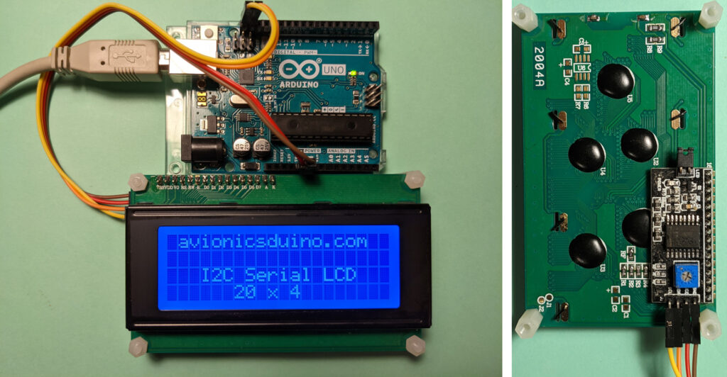
I2C can control a device with just two I/O pins: SDA and SCL. Several devices can coexist on an I2C bus as long as they have different addresses. This bus is relatively slow, ideally suited to sensors but less so to displays. Some alphanumeric monochrome LCDs, such as the one in Figure 3, although having a parallel interface as standard, can be connected to an I2C bus using a parallel-to-I2C interface board soldered on the bottom of the display board.
To display a few lines of text, the I2C bus is more than adequate. A display of this type could have its place on an instrument panel, for example, to display some engine parameters, the position of a trim, the settings of an autopilot, etc.
This well-proven technology, however, has a somewhat austere, old-fashioned look and operates at 5 volts, while recent microcontrollers operate at 3.3 volts.
There are also OLED displays using the I2C bus, often small and with low resolution. They can display short texts or very simple graphics. They can be used with a 3.3-volt power supply.
SPI
Due to the rudimentary, somewhat outdated nature of monochrome alphanumeric LCDs, color graphics displays are generally preferred. TFT technology is by far the most widespread. SPI connection is the most common. TFT displays with a SPI interface use various controllers, including ILI9341, ST7735, HX8357, and RA8875, among others. Their sizes vary from less than 2 inches diagonally up to 7 inches. Their resolutions range from 128 x 160 to 800 x 480 pixels, and some models include a touch interface.
The SPI interface
It is significantly faster than the I2C one. Four wires are required: MISO, MOSI, CLK, and CS. SPI suits the needs of these TFT displays and personal avionics systems quite well. However, this interface has some drawbacks compared to parallel RGB interfaces (see below): there is no synchronization between the microcontroller and the display’s timing signals.
In addition, the controllers of these displays do not embed multiple frame buffers. This can lead to annoying flickering during fast animations, manifested as dark lines or bands that scroll vertically. The animations are to be used sparingly. The best way to avoid flickering is to update only the areas of the screen that change, and keep these changes as limited as possible.
How to prevent flickering?
These prevention principles are impossible to apply in the example of video 1, where a large circular surface is moving. The circle is successively displayed, then erased by drawing an identical circle with the background color (here, black), and then shown again in green at the following location: flickering guaranteed! You should not ever think of programming a video game with moving sprites using a microcontroller and a TFT SPI display!
Avionics displays can do without sprites. However, displaying the artificial horizon of an EFIS can be a real challenge. It is necessary to display many textual and graphic objects (which may vary quickly) on a mobile background representing the sky in blue and the earth in ochre.
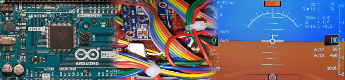
The RA8875 graphic controller
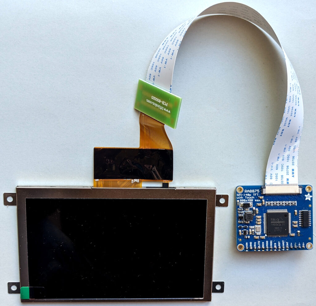
To overcome this difficulty, for our Teensy-based EFIS project, we chose to use a display equipped with an RA8875 controller. The latter serves as an interface between the microcontroller, to which it is connected in SPI, and the TFT panel to which it is connected via a parallel RGB interface (Fig. 4). The RA8875 allows two different layers to be managed separately, each with its dedicated memory, which brings it closer to the principle of double frame buffering. This controller also benefits from an exceptionally efficient and fast library, forked from Sumotoy’s outdated library and optimized for Teensy boards.
The RA8875 library
The main drawback of this library, which is the price to pay for its speed, is that it does not correctly handle attempts to display pixels outside the display resolution’s coordinate bounds. It is up to the programmer to either manage these overruns at the cost of slowing the calculations or to avoid them. The second solution was chosen for our EFIS, which led to a small concession in the usual appearance of an artificial horizon: the pitch graduations rotate with the horizon but do not move vertically with it; see video 2.
Which RA8875 controller to use?
The EastRising / BuyDisplay displays have a few additional features that are not useful for our projects: a microSD slot, SPI Flash memory, and keyboard slots. In addition, they tend to malfunction, for example, when the SPI connection exceeds a few centimeters or when a solderless breadboard is used for testing. Incomprehensible black screens are not uncommon.
For these reasons, we prefer to use the far more reliable Adafruit RA8875 controller and a separate panel, like this one, which has the significant advantage of IPS technology (Wide Viewing Angles). This allows greater flexibility in arranging elements installed on the instrument panel. Indeed, the RA8875 controller board can be integrated onto the same PCB as the Teensy board, ensuring the most reliable and shortest possible SPI connection. Unlike the SPI connection, the parallel RGB connection (40-conductor FFC cable) between the RA8875 controller and the TFT panel can be extended without inconvenience, thanks to a 20 cm extension (Fig. 5). See EFIS page.
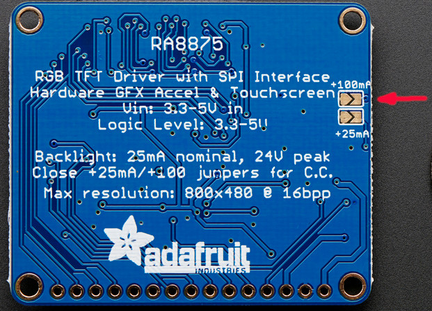
High-brightness 5″ LCD panels require more backlight power current than 4.3″ panels. For this reason, it is necessary to solder the two pads labeled “+100mA” on the back of the RA8875 controller (fig. 6).
Parallel interface
With parallel interfaces (or RGB-parallel), each bit of each color (Red, Green, Blue) is transmitted on a separate line. So 24 lines are required if each color is coded on 8 bits; this is called RGB888 mode. “Only” 16 lines are needed for the RGB565 mode, where Red and Blue are coded on 5 bits and Green on 6 bits. Several other lines are required for vertical and horizontal synchronization, clock signal, etc. And one line implies one pin. So, many microcontroller boards just lack enough pins. And of course, a high computational power and a lot of memory are required to manage all these pins and signals.
The advantage of such a parallel RGB graphic interface, combined with double buffering (one block of data is currently displayed while another is being updated), is its high refresh rate. But this requires a lot of resources, especially memory. In return, it allows fast animations without the slightest flicker.
Is a parallel RGB interface compatible with microcontrollers?
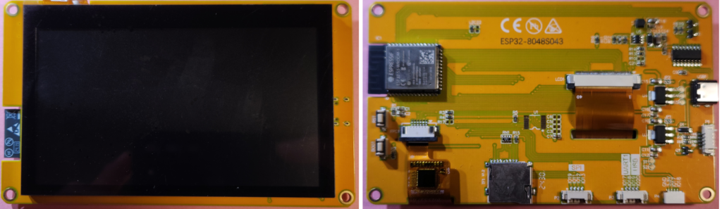
Until recently, this type of interface failed to meet the essential principles outlined on the home page: simplicity and cost-effectiveness. The recent advent of low-cost ESP32 displays, combined with the emergence of two dedicated awesome graphical libraries (TFT_eSPI and LovyanGFX), has radically changed the situation. Figure 7 shows one of these ESP32 displays.
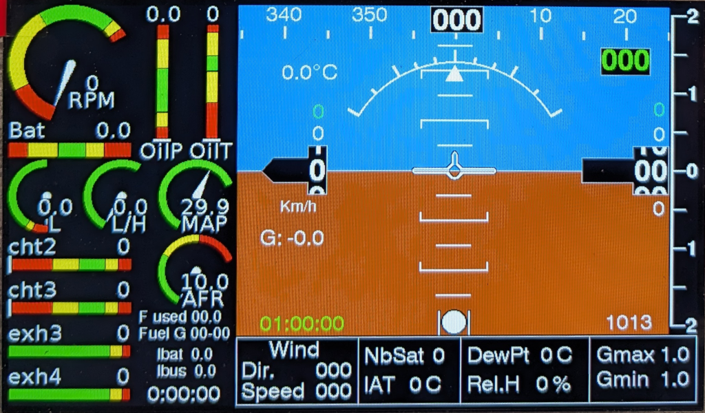
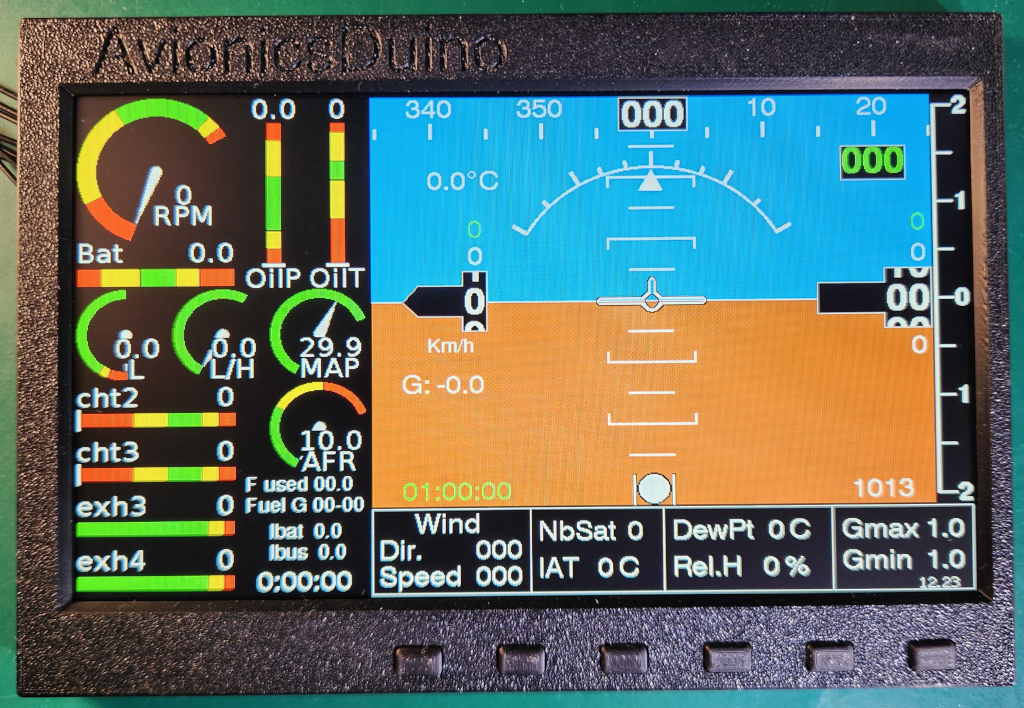
The graphical capabilities of these displays, coupled with the LovyanGFX library (the one we prefer), are outstanding. The extensive use of sprites enables professional-quality, flicker-free animations. A very realistic artificial horizon becomes feasible. Figure 8 shows the new AvionicsDuino ESP32 EFIS-EMS, which has been developed with a 7″ display.
The brightness of all commercially available ESP32 displays is far too low. Furthermore, their glossy touchscreens are highly reflective and difficult to use in turbulent conditions. For these reasons, and specifically for the EFIS-EMS project, a custom ESP32-S3 controller board was developed. It is paired with a 1000 cd/m² non-touch matte TFT panel. This display system is controlled by six push buttons on the front panel. See the “ESP32 EFIS EMS” page. This system uses another ESP32-S3 microcontroller for its Remote Data Acquisition Module (RDAM).
Hi Robert,
Thank you for your kind comments and interesting suggestions. Actually, I installed my aircraft’s electrical system according to Bob Nuckolls’s (Aeroelectric) recommendations, so I have almost no circuit breakers; instead, I mainly use fuses. It’s a fairly simple installation, but very effective and, above all, very safe and secure. And the space on my instrument panel is limited. That’s why I didn’t include a rotary encoder, even though it’s true that it’s more practical for adjusting a numeric value.
The benefit of sharing this type of project is also that everyone can then adapt it to their own constraints and wishes.
I really need to take the time to translate the EFIS-EMS page into English. The ESP32 display section of this new project is ready, and I’ll be able to publish the electrical schematics and Gerber files soon. I’m currently working on the interface board with all the aircraft’s sensors.
Hi Benjamin.
I was looking at your new version on the French site.
I see you have 6 buttons in a frame, I think buttons will be a tremendous advantage over just touchscreen but it would be nice to have both.
I suggest having two or three (or 4) rotary encoders for remote vhf radios and intercom settings, and expand the number of buttons so that, perhaps in the future, they could also be programmed to control electronic circuit breakers. I could see selecting a “button function page” which puts them in electronic circuit breaker mode, displays the breaker label, current limit, ipresent current draw, condition (flipped, on) above on the screen and then long pressing the button allows you to set the current limit of the breaker using one of the rotary encoders, short press would reset the breaker.
Once the switches and rotary encoders are there they can be programmed to do whatever is necessary / desired by the owner / user.
I am sure you’ve considered this and I guess if you are 3D printing the frame it doesn’t matter much what you put on it initially.
Robert,
Thanks again for your comments and suggestions.
Indeed, I’m sure there are plenty of 1000 nits displays on AliExpress/Alibaba; perhaps most are touchscreen (i.e., glossy) and not necessarily IPS (which I think is helpful in an airplane). I agree that touchscreens on an instrument panel can be challenging to use in turbulent conditions.
Our first EFIS-EMS prototype utilized a touchscreen, which is visible on the French page (not yet translated). But the second, as seen in the photo I posted earlier, has a 6-key mini-keyboard.
I purchased a Newhaven Display for my tests to ensure the quality, but if everything works as I hope, I’ll need to find a less expensive solution later, likely on AliExpress or Alibaba.
We share the same reservations about Python, which isn’t really suited to developing an aeronautical graphics application. I tried using Pygame on a Pi 4, and it was horribly slow. It was faster and smoother with Processing, but using the CAN bus and even the UART was not very easy. In comparison, it is relatively straightforward with a microcontroller, such as Arduino, Teensy, or ESP32. Moreover, for the latter, the ESP-NOW protocol and LovyanGFX library are significant advantages.
My PI 4 is now relegated to the sole role of running… Pi-Hole at home! With an excellent success in limiting unwanted publicity. Indeed, a Pi Zero 2W would have been entirely sufficient for that task!
Benjamin
Hello again, Robert,
Actually, I haven’t been home for the past few days and haven’t had time to reply to your message of September 22nd yet.
I’m, of course, familiar with various widget libraries, especially those from huVVer. But it’s not necessarily easier to use other people’s libraries and modify them to suit your own needs rather than starting from scratch to get exactly what you want. That’s what I did for the EFIS-EMS currently in development. By the way, I’ve started writing the French page for this EFIS-EMS, but I haven’t yet found the time to write the English version; that’s, of course, planned.
I’m not familiar enough with embedded versions of Linux that do not have the “power loss” issue, so I have a hard time responding to this specific point. In fact, I don’t have any particular reluctance to the Raspberry Pi – Linux system. Rightly or wrongly, I just have the impression that we can do just as well, and above all simpler, lighter, more reliable, easier to use for readers not necessarily familiar with Linux, with microcontrollers, in particular with ESP32 screen controllers and the LovyanGFX library, which is an improved version of Bodmer’s TFT_e-SPI library. It is also for this exact reason that I probably did not search enough, and therefore did not find the right matte, non-touch, IPS, sunlight-readable screen for the R-Pi.
Benjamin
Hi Benjamin.
Thank you for replying. I saw that display of yours, it looks very good and I look forward to seeing your updates. Thank you for your hard work.
Re – daylight readable displays…there seem to be a lot (that claim to be) 1000+ on AliExpress and Alibaba, although I have not checked all the interfaces but I am researching.
Re – File system corruption on the Pi … there are at least 3 RTOS, read only root file systems available for the Pi in the open source community. This would obviate the need for LifePo4 batteries, would it not ?
The one thing I much prefer of your development is that it is in C++/C, rather than Python which, to me, means better performance, which is why I am much more interested in your efforts than Makerplane, whose pyEFIS is, … in Python 🙂
I already own a couple of Pi’s, one of which I made a “tablet” out of with a 7″ touch screen, in addition to my Stratux device. The one thing I think really is hard to manage in an aircraft is touch screen…my experience here is with the Garmin.
I also have Arduino MEGA and ESP32s now although my ESP32s I am currently developing orchard heater remote monitoring and control. It’s been a while since I did anything at this low level so I’m not going to get anything completed in a hurry but I will setup a development environment and reconnect to github and get a copy of the code so that I can begin studying and understanding it as time allows.
Hi Robert,
Thank you for your comment.
We tested the R-Pi, HDMI, and Processing combination, which allowed us to achieve a beautiful, highly responsive graphical interface. However, on the one hand, it was almost impossible to find an HDMI display bright enough for aeronautical use. On the other hand, in our opinion, adding an uninterruptible power supply with a LiFePO4 battery would introduce significant complexity, bulk, increased cost, and a higher risk of failure, so we decided against pursuing this path.
The Teensy-RA8875 system is straightforward, but it doesn’t allow for such professional-looking graphics, and it’s pretty complex to avoid flickering.
The relatively recent advent of ESP32 displays, such as those used by huVVer, combined with the LovyanGFX library, makes it possible to combine a sunlight-readable display with high-quality graphics and animations, featuring smooth, flicker-free animations. Therefore, this is the path we chose to follow. We anticipate being able to conduct flight tests and publish our results on the website within the coming weeks.
Since commercial ESP32 displays are glossy, which causes a lot of reflections, and they’re never bright enough, we developed our own ESP32-S3 controller to pair it with a non-tactile 1000-nit matte IPS display, usable in direct sunlight on an instrument panel. The picture below shows our EFIS-EMS prototype on a single 7-inch 800 x 480 Newhaven NHD-7.0-800480AF-ASXP display.
More details will be available on the website very soon.
Benjamin
There are a number of open source rtos embedded linux versions that do not have the “power loss” issues mentioned.
There are loads of open source widget libraries.
The Pi4 is pretty cheap.
There are loads of high brightness TFT displays available with various interfaces.
Why the reluctance to use the Pi ? I don’t get it.
Avilution have an EFIS system with a 17″ display and, I think, 1900×1200 with much higher brightness (things change quickly in this business :)).
I would like to emulate their size and format, particularly as I am building a Zenith 750 SD with an Unpanel(tm) arm designed for the Avilution device.
While I have some electronics experience and a career of s/ware development experience, I’m almost obsolete but like a challenge.
The newer Stratux iso uses a read only file system to avoid the corruption common with power loss before shutdown. With this in mind, would it not be cheaper to use a pi4 or 5, even with the cost of the Pi, to run an hdmi (or other common interface), with the Pi ?
I am really interested in EAB avionics and digging into it all over the place and it seems to me you are way ahead of everyone else in this space, with the possible exception of Huvver but they seem to be replacing 6 pack instruments with configurable six pack instruments rather than a single EFIS/EMS display.
“CHEAP” is a very relative term. $80 for a Pi is cheap to me, but perhaps not compared to a Teensy 4.1 board. Then again, if you are building an airplane…
Thanks for the quick reply. I did find the ra8875 on digikey yesterday, I didn’t see it in my earlier searches but probably just missed it. I have a couple on the way.
Thanks again.
Ron
Hello Ron,
Thanks for your kind comment.
Digikey has 133 in stock ! You can order now, you’ll receive the board in 3-4 days.
Unfortunately, there is no satisfactory alternative, the RA8875 is perfectly suited for this task with its two layers, and a highly optimized library is available for Teensy 4.x. Real Time animation of an artificiel horizon over SPI is a true challenge !
Benjamin
Hi,
This project is great work for anyone who’s hobbies include electronics and flying. Great work.
My question is, with the RA8875 controller nearly impossible to find, do you have a reliable second recomendation for a screen driver that you may have tested with the other hardware? Im looking at using the teensy board only for a build but can’t find the 8875 available.
Thank You
Hi Will,
Arduino, Teensy, STM32, and other microcontrollers never have an HDMI socket. An HDMI display would therefore require a single-board computer with HDMI connectivity. The operating system of these single-board computers (usually Linux) does not support sudden power loss, which requires securing this power supply using an uninterruptible power source (UPS). We are considering (with low priority) an EFIS solution based on a Raspberry PI, which would (slightly) improve the overall graphics performance, but the costs and overall complexity would increase significantly.
This would take us away from one of our goals: simplicity and low cost…
Benjamin
Hi,
amazing work, you’ve made me re think my entire panel (:
You had mentioned that perhaps you would be working on a solution for the HDMI screen to run ( display ) EFIS, just curious whether this was something you were still planning on re visiting .
Thank you for sharing all of this, truly brilliant!