(Power supply, last updated by Benjamin on May 08, 2023)
Avionics systems sometimes include several modules. For example, an EFIS, an EMS, an AHRS, and a remote magnetometer. These modules require a low voltage regulated DC power supply, typically 5 volts. To design the architecture of the power system for these modules, two choices must first be made.
Single shared power supply or several individual ones.
There are indeed two alternatives. Either supply each module with 12-14 volts from the aircraft’s main bus, each module having its own step-down regulator, or supply all modules with 5 volts from a single powerful power supply, itself connected to the aircraft’s main bus. Electrical safety requires mounting a fuse or a breaker on the main bus for each module in the first case. In the second case, a single fuse or breaker is sufficient to protect the single wire connecting the main bus to the shared power supply.
In this second case, there are two solutions for the protection of the wires supplying the various modules from the shared power supply. Either mount a fuse of suitable rating on each line or entrust the protection of the whole to the step-down regulator, which must include thermal shutdown and current-limit protection.
For simplicity, we have chosen the second solution. It ideally ensures electrical safety. However, the risk must be assumed that a shorted-to-ground module could cause the entire system to shut down. But on the one hand, this risk is low, and above all, in day VFR (see home page), a failure of the entire system must not have any consequences on the continued safe flight. It is mandatory to have appropriate backup flight and engine monitoring instruments, particularly an altimeter, an anemometer, a compass (or a GPS), a stopwatch, and a tachometer.
Linear or switching regulator
The regulator type choice partly depends on the first choice above. It is not our purpose to explain the theory of the different types of regulators in detail. We will only give a brief reminder of each type’s pros and cons. Knowing that the need is to step down a DC voltage of about 14 volts to 5 volts, with an output current between 1 and 2 amps.
Linear regulators are simple to implement, requiring very few external components (a few low-value decoupling capacitors). Their cost is low. In the absence of switching, they do not generate any significant noise. Their efficiency is low except when the input and output voltages are very close (which is not the case here, the difference between 14 and 5 volts is significant). This low-efficiency results in heat dissipation. The higher the output current required and the voltage step down, the higher the energy loss.
Switching regulators are more complex and expensive, requiring many external components (inductor, diode, and filter capacitors, whose parameters and values must be chosen carefully). Due to high-frequency switching, they may generate noise. But they have excellent conversion efficiency and energy savings; their heat dissipation is low.
The chosen solution
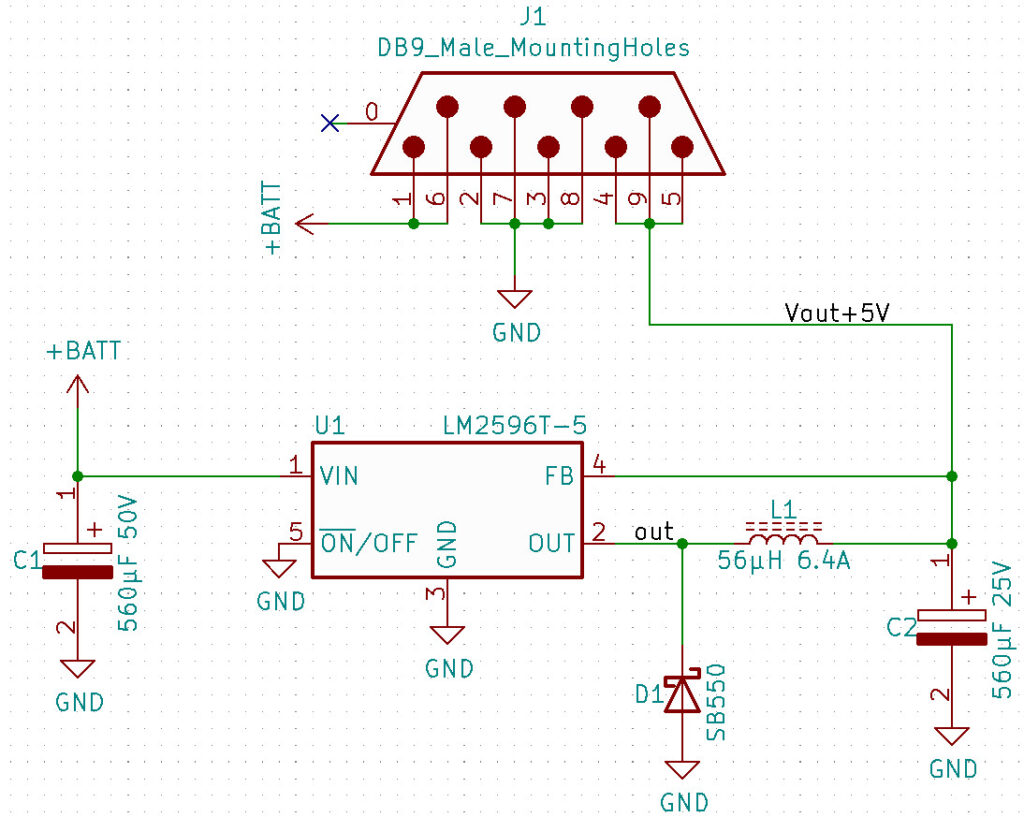
The specifications are as follows: single shared DC power supply, voltage step down from 14 to 5 volts, and output power between 5 and 10 watts. To avoid significant energy dissipation, we have selected the switching regulator solution. Our choice fell on the Texas Instruments LM2596T-5.0 regulator. It is a step-down switching regulator operating at 150 kHz, with a fixed 5 volts output voltage and an output load current of up to 3A.
A careful reading of the datasheet and many tests have led to the diagram below (fig. 1).

Download Gerber and drill files
The disadvantage of using a switching regulator is that the switching actually may create high output ripple and noise. The choice of appropriate capacitors is essential, as are the toroid inductor and the shielding provided by the aluminum enclosure (fig. 2).

